- 您现在的位置:买卖IC网 > PDF目录17334 > ISL6443AEVAL2Z (Intersil)EVALUATION BOARD FOR ISL6443A PDF资料下载
参数资料
| 型号: | ISL6443AEVAL2Z |
| 厂商: | Intersil |
| 文件页数: | 13/19页 |
| 文件大小: | 0K |
| 描述: | EVALUATION BOARD FOR ISL6443A |
| 标准包装: | 1 |
| 主要目的: | DC/DC,LDO 步降 |
| 输出及类型: | 3,非隔离 |
| 输出电压: | 1.8V,3.3V,1.2V |
| 电流 - 输出: | 2A,2A,200mA |
| 输入电压: | 12V |
| 稳压器拓扑结构: | 降压 |
| 频率 - 开关: | 300kHz |
| 板类型: | 完全填充 |
| 已供物品: | 板 |
| 已用 IC / 零件: | ISL6443A |
�� �
�
�ISL6443A�
�(� 7� )� (� R� CS� )�
�(� I� OC� )� (� r� DS� (� on� )� )�
�(EQ.� 5)�
�R� OCSET� =� -----------------------------------------�
�where,� I� OC� is� the� desired� overcurrent� protection� threshold,�
�and� R� CS� is� a� value� of� the� current� sense� resistor� connected� to�
�the� ISENx� pin.� If� an� overcurrent� is� detected� for� 2� consecutive�
�clock� cycles,� then� the� IC� enters� a� hiccup� mode� by� turning� off�
�the� gate� drivers� and� entering� into� soft-start.� The� IC� will� cycle�
�2x� through� soft-start� before� trying� to� restart.� The� IC� will�
�continue� to� cycle� through� soft-start� until� the� overcurrent�
�condition� is� removed.� Hiccup� mode� is� active� during� soft-start,�
�so� care� must� be� taken� to� ensure� that� the� peak� inductor� current�
�does� not� exceed� the� overcurrent� threshold� during� soft-start.�
�Because� of� the� nature� of� this� current� sensing� technique,� and�
�to� accommodate� a� wide� range� of� r� DS(ON)� variations,� the�
�value� of� the� overcurrent� threshold� should� represent� an�
�overload� current� about� 150%� to� 180%� of� the� maximum�
�operating� current.� If� more� accurate� current� protection� is�
�desired,� place� a� current� sense� resistor� in� series� with� the�
�Feedback� Loop� Compensation�
�To� reduce� the� number� of� external� components� and� to� simplify�
�the� process� of� determining� compensation� components,� both�
�PWM� controllers� have� internally� compensated� error�
�amplifiers.� To� make� internal� compensation� possible,� several�
�design� measures� were� taken.�
�First,� the� ramp� signal� applied� to� the� PWM� comparator� is�
�proportional� to� the� input� voltage� provided� via� the� VIN� pin.�
�This� keeps� the� modulator� gain� constant� with� variation� in� the�
�input� voltage.� Second,� the� load� current� proportional� signal� is�
�derived� from� the� voltage� drop� across� the� lower� MOSFET�
�during� the� PWM� time� interval� and� is� subtracted� from� the�
�amplified� error� signal� on� the� comparator� input.� This� creates�
�an� internal� current� control� loop.� The� resistor� connected� to�
�the� ISEN� pin� sets� the� gain� in� the� current� feedback� loop.�
�Equation� 6� estimates� the� required� value� of� the� current� sense�
�resistor� depending� on� the� maximum� operating� load� current�
�and� the� value� of� the� MOSFET’s� r� DS(ON)� .�
�(� I� MAX� )� (� r� DS� (� ON� )� )�
�lower� MOSFET� source.�
�Over-Temperature� Protection�
�32� μ� A�
�R� CS� ≥� -----------------------------------------------�
�(EQ.� 6)�
�The� IC� incorporates� an� over-temperature� protection� circuit�
�that� shuts� the� IC� down� when� a� die� temperature� of� +150°C�
�is� reached.� Normal� operation� resumes� when� the� die�
�temperatures� drops� below� +130°C� through� the� initiation� of�
�a� full� soft-start� cycle.�
�Implementing� Synchronization�
�Choosing� R� CS� to� provide� 32μA� of� current� to� the� current�
�sample� and� hold� circuitry� is� recommended� but� values� down�
�to� 2μA� and� up� to� 100μA� can� be� used.�
�Due� to� the� current� loop� feedback,� the� modulator� has� a� single�
�pole� response� with� -20dB� slope� at� a� frequency� determined�
�by� the� load.�
�F� PO� =� ---------------------------------�
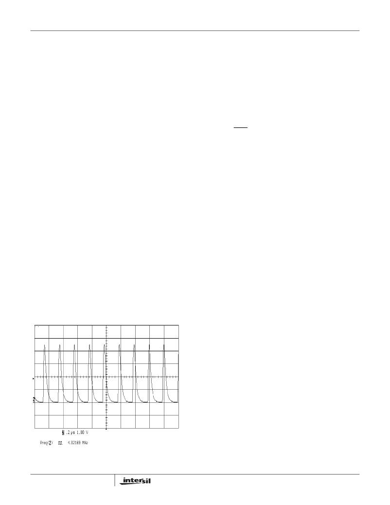
�The� SYNC� pin� may� be� used� to� synchronize� two� or� more�
�controllers.� When� the� SYNC� pins� of� two� controllers� are�
�1�
�2� π� ?� R� O� ?� C� O�
�(EQ.� 7)�
�connected� together,� one� controller� becomes� the� master� and�
�the� other� controller� synchronizes� to� the� master.� A� pull-down�
�resistor� is� required� and� must� be� sized� to� provide� a� low�
�enough� time� constant� to� pass� the� SYNC� pulse.� Connect� this�
�pin� to� VCC_5V� if� not� used.� Figure� 16� shows� the� SYNC� pin�
�waveform� operating� at� 16x� the� switching� frequency.�
�where� R� O� is� load� resistance� and� C� O� is� load� capacitance.� For�
�this� type� of� modulator,� a� Type� 2� compensation� circuit� is�
�usually� sufficient.�
�Figure� 17� shows� a� Type� 2� amplifier� and� its� response� along�
�with� the� responses� of� the� current� mode� modulator� and� the�
�converter.� The� Type� 2� amplifier,� in� addition� to� the� pole� at�
�origin,� has� a� zero-pole� pair� that� causes� a� flat� gain� region� at�
�frequencies� in� between� the� zero� and� the� pole.�
�F� Z� =� -------------------------------� =� 6kHz�
�F� P� =� -------------------------------� =� 600kHz�
�FIGURE� 16.� SYNC� WAVEFORM�
�13�
�1�
�2� π� ?� R� 2� ?� C� 1�
�1�
�2� π� ?� R� 1� ?� C� 2�
�(EQ.� 8)�
�(EQ.� 9)�
�FN6600.2�
�June� 2,� 2008�
�相关PDF资料 |
PDF描述 |
|---|---|
| A9BBG-1304F | FLEX CABLE - AFF13G/AF13/AFF13G |
| EEC15DRTI-S13 | CONN EDGECARD 30POS .100 EXTEND |
| EEC20DRTH-S13 | CONN EDGECARD 40POS .100 EXTEND |
| ECC08DRTH-S13 | CONN EDGECARD 16POS .100 EXTEND |
| IPS511GTR | IC MOSFET HS PWR SW 5A 8-SOIC |
相关代理商/技术参数 |
参数描述 |
|---|---|
| ISL6443AIRZ | 功能描述:IC CTRLR SGL/STEP DOWN PWM 28QFN RoHS:是 类别:集成电路 (IC) >> PMIC - 电源管理 - 专用 系列:- 产品培训模块:Lead (SnPb) Finish for COTS Obsolescence Mitigation Program 标准包装:50 系列:- 应用:热电冷却器 电流 - 电源:- 电源电压:3 V ~ 5.5 V 工作温度:-40°C ~ 85°C 安装类型:表面贴装 封装/外壳:28-SOIC(0.173",4.40mm 宽)裸露焊盘 供应商设备封装:28-TSSOP 裸露焊盘 包装:管件 产品目录页面:1410 (CN2011-ZH PDF) |
| ISL6443AIRZ-TK | 功能描述:IC CTRLR SGL/STP DWN PWM 28-QFN RoHS:是 类别:集成电路 (IC) >> PMIC - 电源管理 - 专用 系列:- 应用说明:Ultrasound Imaging Systems Application Note 产品培训模块:Lead (SnPb) Finish for COTS Obsolescence Mitigation Program 标准包装:37 系列:- 应用:医疗用超声波成像,声纳 电流 - 电源:- 电源电压:2.37 V ~ 6 V 工作温度:0°C ~ 70°C 安装类型:表面贴装 封装/外壳:56-WFQFN 裸露焊盘 供应商设备封装:56-TQFN-EP(8x8) 包装:管件 |
| ISL6443AIVZ | 功能描述:IC CTRLR SGL/STP DWN PWM 28TSSOP RoHS:是 类别:集成电路 (IC) >> PMIC - 电源管理 - 专用 系列:- 应用说明:Ultrasound Imaging Systems Application Note 产品培训模块:Lead (SnPb) Finish for COTS Obsolescence Mitigation Program 标准包装:37 系列:- 应用:医疗用超声波成像,声纳 电流 - 电源:- 电源电压:2.37 V ~ 6 V 工作温度:0°C ~ 70°C 安装类型:表面贴装 封装/外壳:56-WFQFN 裸露焊盘 供应商设备封装:56-TQFN-EP(8x8) 包装:管件 |
| ISL6443AIVZ-TK | 功能描述:IC CTRLR SGL/STP DWN PWM 28TSSOP RoHS:是 类别:集成电路 (IC) >> PMIC - 电源管理 - 专用 系列:- 应用说明:Ultrasound Imaging Systems Application Note 产品培训模块:Lead (SnPb) Finish for COTS Obsolescence Mitigation Program 标准包装:37 系列:- 应用:医疗用超声波成像,声纳 电流 - 电源:- 电源电压:2.37 V ~ 6 V 工作温度:0°C ~ 70°C 安装类型:表面贴装 封装/外壳:56-WFQFN 裸露焊盘 供应商设备封装:56-TQFN-EP(8x8) 包装:管件 |
| ISL6443IR | 功能描述:IC CTRLR SGL/STEP DOWN PWM 28QFN RoHS:否 类别:集成电路 (IC) >> PMIC - 电源管理 - 专用 系列:- 应用说明:Ultrasound Imaging Systems Application Note 产品培训模块:Lead (SnPb) Finish for COTS Obsolescence Mitigation Program 标准包装:37 系列:- 应用:医疗用超声波成像,声纳 电流 - 电源:- 电源电压:2.37 V ~ 6 V 工作温度:0°C ~ 70°C 安装类型:表面贴装 封装/外壳:56-WFQFN 裸露焊盘 供应商设备封装:56-TQFN-EP(8x8) 包装:管件 |
发布紧急采购,3分钟左右您将得到回复。