- 您现在的位置:买卖IC网 > PDF目录15062 > ISL6569CB (Intersil)IC REG CTRLR DIVIDER PWM 24-SOIC PDF资料下载
参数资料
| 型号: | ISL6569CB |
| 厂商: | Intersil |
| 文件页数: | 20/22页 |
| 文件大小: | 0K |
| 描述: | IC REG CTRLR DIVIDER PWM 24-SOIC |
| 标准包装: | 30 |
| PWM 型: | 控制器 |
| 输出数: | 1 |
| 频率 - 最大: | 2MHz |
| 占空比: | 75% |
| 电源电压: | 4.75 V ~ 5.25 V |
| 降压: | 是 |
| 升压: | 无 |
| 回扫: | 无 |
| 反相: | 无 |
| 倍增器: | 无 |
| 除法器: | 是 |
| Cuk: | 无 |
| 隔离: | 无 |
| 工作温度: | 0°C ~ 70°C |
| 封装/外壳: | 24-SOIC(0.295",7.50mm 宽) |
| 包装: | 管件 |
�� �
�
�ISL6569�
�0.3�
�0.2�
�0.1�
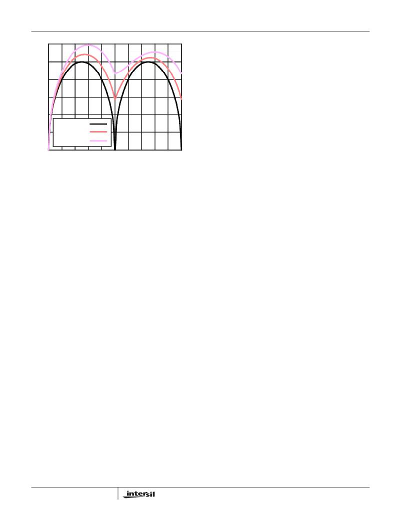
�I� C,PP� =� 0�
�I� C,PP� =� 0.5� I� O�
�I� C,PP� =� 0.75� I� O�
�Next,� place� the� input� and� output� capacitors.� Position� one�
�high-frequency� ceramic� input� capacitor� next� to� each� upper�
�MOSFET� drain.� Place� the� bulk� input� capacitors� as� close� to�
�the� upper� MOSFET� drains� as� dictated� by� the� component�
�size� and� dimensions.� Long� distances� between� input�
�capacitors� and� MOSFET� drains� results� in� too� much� trace�
�inductance� and� a� reduction� in� capacitor� performance.� Locate�
�the� output� capacitors� between� the� inductors� and� the� load,�
�while� keeping� them� in� close� proximity� around� the�
�microprocessor� socket.�
�The� ISL6569� can� be� placed� off� to� one� side� or� centered�
�relative� to� the� individual� phase� switching� components.�
�Routing� of� sense� lines� and� PWM� signals� will� guide� final�
�0�
�0�
�0.2�
�0.4� 0.6�
�DUTY� CYCLE� (V� IN� /� V� O� )�
�0.8�
�1.0�
�placement.� Critical� small� signal� components� to� place� close�
�to� the� controller� include� the� ISEN� resistors,� R� T� resistor,�
�feedback� resistor,� and� compensation� components.�
�FIGURE� 16.� NORMALIZED� INPUT-CAPACITOR� RMS� CURRENT�
�VS� DUTY� CYCLE� FOR� 2-PHASE� CONVERTER�
�For� a� two� phase� design,� use� Figure� 16� to� determine� the�
�input-capacitor� RMS� current� requirement� given� the� duty�
�cycle,� maximum� sustained� output� current� (I� O� ),� and� the� ratio�
�of� the� combined� peak-to-peak� inductor� current� (I� C,PP� )� to� I� O� .�
�Select� a� bulk� capacitor� with� a� ripple� current� rating� which� will�
�minimize� the� total� number� of� input� capacitors� required� to�
�support� the� RMS� current� calculated.� The� voltage� rating� of�
�the� capacitors� should� also� be� at� least� 1.25� times� greater�
�than� the� maximum� input� voltage.�
�Layout� Considerations�
�The� following� multi-layer� printed� circuit� board� layout� strategies�
�minimize� the� impact� of� board� parasitics� on� converter�
�performance.� The� following� sections� highlight� some� important�
�practices� which� should� not� be� overlooked� during� the� layout�
�process.�
�Component� Placement�
�Within� the� allotted� implementation� area,� orient� the� switching�
�components� first.� The� switching� components� are� the� most�
�critical� because� they� switch� large� amounts� of� energy� and�
�tend� to� generate� large� amounts� of� noise.� How� the� switching�
�components� are� placed� should� also� take� into� account� power�
�dissipation.� Align� the� output� inductors� and� MOSFETs� such�
�that� space� between� the� components� is� minimized� while�
�creating� the� PHASE� plane.� Place� the� Intersil� HIP660X�
�drivers� as� close� as� possible� to� the� MOSFETs� they� control� to�
�reduce� the� parasitics� due� to� trace� length� between� critical�
�driver� input� and� output� signals.� If� possible,� duplicate� the�
�same� placement� of� switching� components� for� each� phase.�
�20�
�Bypass� capacitors� for� the� ISL6569� and� HIP660X� driver� bias�
�supplies� must� be� placed� next� to� their� respective� pins.� Stray�
�trace� parasitics� will� reduce� their� effectiveness.�
�Plane� Allocation� and� Routing�
�Dedicate� one� solid� layer,� usually� a� middle� layer,� for� a� ground�
�plane.� Make� all� critical� component� ground� connections� with�
�vias� to� this� plane.� Dedicate� one� additional� layer� for� power�
�planes;� breaking� the� plane� up� into� smaller� islands� of�
�common� voltage.� Use� the� remaining� layers� for� small� signal�
�wiring.�
�Route� PHASE� planes� of� copper� filled� polygons� on� the� top�
�and� bottom� once� the� switching� component� placement� is� set.�
�Size� the� trace� width� between� the� driver� gate� pins� and� the�
�MOSFET� gates� to� carry� 1A� of� current.� When� routing�
�components� in� the� switching� path,� use� short� wide� traces� to�
�reduce� the� associated� parasitics.�
�FN9085.7�
�December� 29,� 2004�
�相关PDF资料 |
PDF描述 |
|---|---|
| VI-B5N-EV-F4 | CONVERTER MOD DC/DC 18.5V 150W |
| VI-JTR-EY-F2 | CONVERTER MOD DC/DC 7.5V 50W |
| ISL6565BCV | IC REG CTRLR BUCK PWM VM 28TSSOP |
| VI-JTR-EY-F1 | CONVERTER MOD DC/DC 7.5V 50W |
| VI-B5M-EV-F4 | CONVERTER MOD DC/DC 10V 150W |
相关代理商/技术参数 |
参数描述 |
|---|---|
| ISL6569CB-T | 功能描述:IC REG CTRLR DIVIDER PWM 24-SOIC RoHS:否 类别:集成电路 (IC) >> PMIC - 稳压器 - DC DC 切换控制器 系列:- 标准包装:2,500 系列:- PWM 型:电流模式 输出数:1 频率 - 最大:500kHz 占空比:100% 电源电压:8.2 V ~ 30 V 降压:无 升压:无 回扫:是 反相:无 倍增器:无 除法器:无 Cuk:无 隔离:是 工作温度:0°C ~ 70°C 封装/外壳:8-DIP(0.300",7.62mm) 包装:管件 产品目录页面:1316 (CN2011-ZH PDF) |
| ISL6569CBZ | 功能描述:IC REG CTRLR DIVIDER PWM 24-SOIC RoHS:是 类别:集成电路 (IC) >> PMIC - 稳压器 - DC DC 切换控制器 系列:- 产品培训模块:Lead (SnPb) Finish for COTS Obsolescence Mitigation Program 标准包装:2,500 系列:- PWM 型:电流模式 输出数:1 频率 - 最大:275kHz 占空比:50% 电源电压:18 V ~ 110 V 降压:无 升压:无 回扫:无 反相:无 倍增器:无 除法器:无 Cuk:无 隔离:是 工作温度:-40°C ~ 85°C 封装/外壳:8-SOIC(0.154",3.90mm 宽) 包装:带卷 (TR) |
| ISL6569CBZ-T | 功能描述:IC REG CTRLR DIVIDER PWM 24-SOIC RoHS:是 类别:集成电路 (IC) >> PMIC - 稳压器 - DC DC 切换控制器 系列:- 产品培训模块:Lead (SnPb) Finish for COTS Obsolescence Mitigation Program 标准包装:2,500 系列:- PWM 型:电流模式 输出数:1 频率 - 最大:275kHz 占空比:50% 电源电压:18 V ~ 110 V 降压:无 升压:无 回扫:无 反相:无 倍增器:无 除法器:无 Cuk:无 隔离:是 工作温度:-40°C ~ 85°C 封装/外壳:8-SOIC(0.154",3.90mm 宽) 包装:带卷 (TR) |
| ISL6569CR | 功能描述:IC REG CTRLR DIVIDER PWM 32-QFN RoHS:否 类别:集成电路 (IC) >> PMIC - 稳压器 - DC DC 切换控制器 系列:- 标准包装:2,500 系列:- PWM 型:电流模式 输出数:1 频率 - 最大:500kHz 占空比:100% 电源电压:8.2 V ~ 30 V 降压:无 升压:无 回扫:是 反相:无 倍增器:无 除法器:无 Cuk:无 隔离:是 工作温度:0°C ~ 70°C 封装/外壳:8-DIP(0.300",7.62mm) 包装:管件 产品目录页面:1316 (CN2011-ZH PDF) |
| ISL6569CR-T | 功能描述:IC REG CTRLR DIVIDER PWM 32-QFN RoHS:否 类别:集成电路 (IC) >> PMIC - 稳压器 - DC DC 切换控制器 系列:- 标准包装:2,500 系列:- PWM 型:电流模式 输出数:1 频率 - 最大:500kHz 占空比:100% 电源电压:8.2 V ~ 30 V 降压:无 升压:无 回扫:是 反相:无 倍增器:无 除法器:无 Cuk:无 隔离:是 工作温度:0°C ~ 70°C 封装/外壳:8-DIP(0.300",7.62mm) 包装:管件 产品目录页面:1316 (CN2011-ZH PDF) |
发布紧急采购,3分钟左右您将得到回复。