- 您现在的位置:买卖IC网 > PDF目录17336 > ISL6740EVAL1 (Intersil)EVALUATION BOARD 1 ISL6740 PDF资料下载
参数资料
| 型号: | ISL6740EVAL1 |
| 厂商: | Intersil |
| 文件页数: | 18/28页 |
| 文件大小: | 0K |
| 描述: | EVALUATION BOARD 1 ISL6740 |
| 标准包装: | 1 |
| 主要目的: | DC/DC,步降 |
| 输出及类型: | 1,非隔离 |
| 输出电压: | 12V |
| 电流 - 输出: | 8A |
| 输入电压: | 48V |
| 稳压器拓扑结构: | 降压 |
| 板类型: | 完全填充 |
| 已供物品: | 板 |
| 已用 IC / 零件: | ISL6740 |
第1页第2页第3页第4页第5页第6页第7页第8页第9页第10页第11页第12页第13页第14页第15页第16页第17页当前第18页第19页第20页第21页第22页第23页第24页第25页第26页第27页第28页
�� �
�
�ISL6740,� ISL6741�
�determined� by� measurement,� calculation,� estimate,� or� by� some�
�combination� of� these� methods.�
�V� OUT� is� the� output� voltage�
�If� we� allow� a� current� ramp,� Δ� I,� of� 5%� of� the� rated� output� current,�
�t� zvs� ≈� ------------------------------------------------------------------�
�π� L� lk� ?� (� 2C� oss� +� C� xfrmr� )� (EQ.� 19)�
�2�
�V� L� ?� T� ON� 0.25� ?� 2.08�
�Δ� I�
�L� ≥� ----------------------� =� -----------------------------� =� 1.04�
�S�
�Device� output� capacitance,� Coss,� is� non-linear� with� applied�
�the� minimum� inductance� required� is:�
�0.5�
�μ� H�
�(EQ.� 23)�
�voltage.� To� find� the� equivalent� discrete� capacitance,� Cfet,� a�
�charge� model� is� used.� Using� a� known� current� source,� the� time�
�required� to� charge� the� MOSFET� drain� to� the� desired� operating�
�voltage� is� determined� and� the� equivalent� capacitance� is�
�calculated.�
�An� inductor� value� of� 1.4� μ� H,� rated� for� 18A� was� selected.�
�With� a� maximum� input� voltage� of� 53V,� the� maximum� output�
�voltage� is� about� 13V.� The� closest� higher� voltage� rated� capacitor�
�is� 16V.� Under� steady� state� operating� conditions� the� ripple� current�
�Ichg� ?� t�
�Cfet� =� -------------------�
�V�
�F�
�(EQ.� 20)�
�in� the� capacitor� is� small,� so� it� would� seem� appropriate� to� have� a�
�low� ripple� current� rated� capacitor.� However,� a� high� rated� ripple�
�current� capacitor� was� selected� based� on� the� nature� of� the�
�Once� the� estimated� transition� time� is� determined,� it� must� be�
�verified� directly� in� the� application.� The� transformer� leakage�
�inductance� was� measured� at� 125nH� and� the� combined�
�capacitance� was� estimated� at� 2000pF.� Calculations� indicate� a�
�transition� period� of� ~� 25ns.� Verification� of� the� performance�
�yielded� a� value� of� t� D� closer� to� 45ns.�
�The� remainder� of� the� switching� half-period� is� the� charge� time,� t� C� ,�
�and� can� be� found� from�
�intended� load,� multiple� buck� regulators.� To� minimize� the� output�
�impedance� of� the� filter,� a� Sanyo� OSCON� 16SH150M� capacitor� in�
�parallel� with� a� 22� μ� F� ceramic� capacitor� were� selected.�
�Overcurrent� Component� Selection�
�There� are� two� circuit� areas� to� consider� when� selecting� the�
�components� for� overcurrent� protection,� current� limit� and� short�
�circuit� shutdown.� The� current� limit� threshold� is� fixed� at� 0.6V� while�
�the� short� circuit� threshold� is� set� to� a� fraction� of� the� duty� cycle� the�
�t� C� =� ---------------� –� t� D� =� -----------------------------------� –� 45� ?� 10�
�2� ?� F� S�
�2� ?� 235� ?� 10�
�1� 1�
�3�
�–� 9�
�=� 2.08�
�μ� s�
�(EQ.� 21)�
�designer� wishes� to� define� as� a� short� circuit.�
�The� current� level� that� corresponds� to� the� overcurrent� threshold�
�must� be� chosen� to� allow� for� the� dynamic� behavior� of� an� open�
�where� F� S� is� the� converter� switching� frequency.�
�Using� Figure� 4,� the� capacitor� value� appropriate� to� the� desired�
�oscillator� operating� frequency� of� 470kHz� can� be� selected.� A� C� T�
�value� of� 100pF,� 220pF,� or� 330pF� is� appropriate� for� this�
�loop� converter.� In� particular,� the� low� inductor� ripple� current� under�
�steady� state� operation� increases� significantly� as� the� duty� cycle�
�decreases.�
�14�
�frequency.� A� value� of� 220pF� was� selected.�
�To� obtain� the� proper� value� for� R� TD� ,� Equation� 3� is� used.� Since�
�there� is� a� 10ns� propagation� delay� in� the� oscillator� circuit,� it� must�
�be� included� in� the� calculation.� The� value� of� R� TD� selected� is�
�8.06k� Ω� .�
�A� similar� procedure� is� used� to� determine� the� value� of� R� TC� using�
�Equation� 2.� The� value� of� R� TC� selected� is� the� series� combination� of�
�17.4k� Ω� and� 1.27k� Ω� .� See� section� “Overcurrent� Component�
��13�
�12�
�11�
�10�
�9�
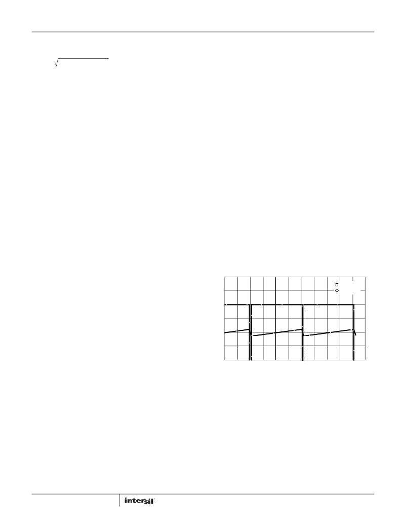
�V� (L1:1)�
�I� (L1)�
�Output� Filter� Design�
�8�
�0.9950�
�0.9960�
�0.9970�
�0.9980�
�0.9990�
�1.000�
�The� output� filter� inductor� and� capacitor� selection� is� simple� and�
�straightforward.� Under� steady� state� operating� conditions� the�
�voltage� across� the� inductor� is� very� small� due� to� the� large� duty�
�cycle.� Voltage� is� applied� across� the� inductor� only� during� the�
�switch� transition� time,� about� 45ns� in� this� application.� Ignoring�
�the� voltage� drop� across� the� SR� FETs,� the� voltage� across� the�
�inductor� during� the� ON� time� with� V� IN� =� 48V� is:�
�TIME� (ms)�
�FIGURE� 8.� STEADY� STATE� SECONDARY� WINDING� VOLTAGE�
�AND� INDUCTOR� CURRENT�
�V� IN� ?� N� S� ?� (� 1� –� D� )�
�V� L� =� V� S� –� V� OUT� =� ---------------------------------------------� ≈� 250�
�2N� P�
�mV�
�(EQ.� 22)�
�where�
�V� L� is� the� inductor� voltage�
�V� S� is� the� voltage� across� the� secondary� winding�
�18�
�FN9111.6�
�December� 2,� 2011�
�相关PDF资料 |
PDF描述 |
|---|---|
| EEC30DRXH | CONN EDGECARD 60POS DIP .100 SLD |
| ISL6527EVAL2 | EVALUATION BOARD QFN ISL6527 |
| HK10052N2S-T | INDUCTOR HIFREQ 2.2+/-0.3NH 0402 |
| ISL6527AEVAL2 | EVALUATION BOARD QFN ISL6527A |
| 594D476X0010B8T | CAP TANT 47UF 10V 20% 1611 |
相关代理商/技术参数 |
参数描述 |
|---|---|
| ISL6740EVAL2 | 功能描述:EVALUATION BOARD 2 ISL6740 RoHS:否 类别:编程器,开发系统 >> 过时/停产零件编号 系列:- 标准包装:1 系列:- 传感器类型:CMOS 成像,彩色(RGB) 传感范围:WVGA 接口:I²C 灵敏度:60 fps 电源电压:5.7 V ~ 6.3 V 嵌入式:否 已供物品:成像器板 已用 IC / 零件:KAC-00401 相关产品:4H2099-ND - SENSOR IMAGE WVGA COLOR 48-PQFP4H2094-ND - SENSOR IMAGE WVGA MONO 48-PQFP |
| ISL6740EVAL2Z | 功能描述:EVALUATION BOARD 2 ISL6740 RoHS:是 类别:编程器,开发系统 >> 评估板 - DC/DC 与 AC/DC(离线)SMPS 系列:- 产品培训模块:Obsolescence Mitigation Program 标准包装:1 系列:True Shutdown™ 主要目的:DC/DC,步升 输出及类型:1,非隔离 功率 - 输出:- 输出电压:- 电流 - 输出:1A 输入电压:2.5 V ~ 5.5 V 稳压器拓扑结构:升压 频率 - 开关:3MHz 板类型:完全填充 已供物品:板 已用 IC / 零件:MAX8969 |
| ISL6740EVAL3Z | 制造商:Intersil Corporation 功能描述:ISL6740 EVALUATION BOARD 3 - ROHS COMPLIANT - SOIC - DSL - Bulk 制造商:Intersil Corporation 功能描述:Power Management IC Development Tools ISL6740 EVAL RD 3 ROHS CMPL DSL |
| ISL6740IB | 功能描述:IC REG CTRLR PWM VM 16-SOIC RoHS:否 类别:集成电路 (IC) >> PMIC - 稳压器 - DC DC 切换控制器 系列:- 标准包装:2,500 系列:- PWM 型:电流模式 输出数:1 频率 - 最大:500kHz 占空比:100% 电源电压:8.2 V ~ 30 V 降压:无 升压:无 回扫:是 反相:无 倍增器:无 除法器:无 Cuk:无 隔离:是 工作温度:0°C ~ 70°C 封装/外壳:8-DIP(0.300",7.62mm) 包装:管件 产品目录页面:1316 (CN2011-ZH PDF) |
| ISL6740IB-T | 功能描述:IC REG CTRLR PWM VM 16-SOIC RoHS:否 类别:集成电路 (IC) >> PMIC - 稳压器 - DC DC 切换控制器 系列:- 标准包装:2,500 系列:- PWM 型:电流模式 输出数:1 频率 - 最大:500kHz 占空比:100% 电源电压:8.2 V ~ 30 V 降压:无 升压:无 回扫:是 反相:无 倍增器:无 除法器:无 Cuk:无 隔离:是 工作温度:0°C ~ 70°C 封装/外壳:8-DIP(0.300",7.62mm) 包装:管件 产品目录页面:1316 (CN2011-ZH PDF) |
发布紧急采购,3分钟左右您将得到回复。