- 您现在的位置:买卖IC网 > PDF目录15772 > ISL6744EVAL1 (Intersil)EVALUATION BOARD ISL6744 PDF资料下载
参数资料
| 型号: | ISL6744EVAL1 |
| 厂商: | Intersil |
| 文件页数: | 10/18页 |
| 文件大小: | 0K |
| 描述: | EVALUATION BOARD ISL6744 |
| 标准包装: | 1 |
| 主要目的: | DC/DC,步降 |
| 输出及类型: | 1,隔离 |
| 功率 - 输出: | 100W |
| 输出电压: | 12V |
| 电流 - 输出: | 8A |
| 输入电压: | 43.2 ~ 52.8V |
| 稳压器拓扑结构: | 降压 |
| 频率 - 开关: | 235kHz |
| 板类型: | 完全填充 |
| 已供物品: | 板 |
| 已用 IC / 零件: | ISL6744 |
�� �
�
�ISL6744�
�windings� would� also� be� acceptable,� but� the� gate� drive� losses�
�would� increase.�
�The� next� step� is� to� determine� the� equivalent� wire� gauge� for�
�the� planar� structure.� Since� each� secondary� winding�
�conducts� for� only� 50%� of� the� period,� the� RMS� current� is�
�The� primary� windings� have� an� RMS� current� of� approximately�
�5� A� (I� OUT� x� N� S� /N� P� at� ~� 100%� duty� cycle).� The� primary� is�
�configured� as� 2� layers,� 2� turns� per� layer� to� minimize� the�
�winding� stack� height.� Allowing� 0.020� inches� edge� clearance�
�and� 0.010� inches� between� turns� yields� a� trace� width� of�
�0.0575� inches.� Ignoring� the� terminal� and� lead-in� resistance,�
�I� RMS� =� I� OUT� ?� D� =� 10� ?� 0.5� =� 7.07�
�A�
�(EQ.� 10)�
�and� using� EQ.� 11,� the� inner� trace� has� a� resistance� of�
�4.25m� Ω� ,� and� the� outer� trace� has� a� resistance� of� 5.52m� Ω� .�
�where� D� is� the� duty� cycle.� Since� an� FR-4� PWB� planar�
�winding� structure� was� selected,� the� width� of� the� copper�
�traces� is� limited� by� the� window� area� width,� and� the� number�
�of� layers� is� limited� by� the� window� area� height.� The� PQ� core�
�selected� has� a� usable� window� area� width� of� 0.165� inches.�
�Allowing� one� turn� per� layer� and� 0.020� inches� clearance� at�
�the� edges� allows� a� maximum� trace� width� of� 0.125� inches.�
�Using� 100� circular� mils(c.m.)/A� as� a� guideline� for� current�
�density,� and� from� EQ.� 10,� 707c.m.� are� required� for� each� of�
�the� secondary� windings� (a� circular� mil� is� the� area� of� a� circle�
�0.001� inches� in� diameter).� Converting� c.m.� to� square� mils�
�yields� 555mils� 2� (0.785� sq.� mils/c.m.).� Dividing� by� the� trace�
�width� results� in� a� copper� thickness� of� 4.44mils� (0.112mm).�
�Using� 1.3mils/oz.� of� copper� requires� a� copper� weight� of�
�3.4oz.� For� reasons� of� cost,� 3oz.� copper� was� selected.�
�One� layer� of� each� secondary� winding� also� contains� the�
�synchronous� rectifier� winding.� For� this� layer� the� secondary�
�trace� width� is� reduced� by� 0.025� inches� to� 0.100� inches(0.015�
�inches� for� the� SR� winding� trace� width� and� 0.010� inches�
�spacing� between� the� SR� winding� and� the� secondary�
�winding).�
�The� choice� of� copper� weight� may� be� validated� by� calculating�
�the� DC� copper� losses� of� the� secondary� winding.� Ignoring� the�
�terminal� and� lead-in� resistance,� the� resistance� of� each� layer�
�of� the� secondary� may� be� approximated� using� EQ.� 11.�
�The� resistance� of� the� primary� then� is� 19.5m� Ω� at� 20°C.� The�
�total� DC� power� loss� for� the� primary� at� 20°C� is� 489mW.�
�Improved� efficiency� and� thermal� performance� could� be�
�achieved� by� selecting� heavier� copper� weight� for� the�
�windings.� Evaluation� in� the� application� will� determine� its�
�need.�
�The� order� and� geometry� of� the� windings� affects� the� AC�
�resistance,� winding� capacitance,� and� leakage� inductance� of�
�the� finished� transformer.� To� mitigate� these� effects,�
�interleaving� the� windings� is� necessary.� The� primary� winding�
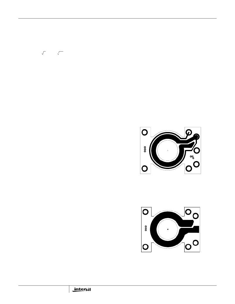
�is� sandwiched� between� the� two� secondary� windings.� The�
�winding� layout� appears� below.�
�FIGURE� 7A.� TOP� LAYER:� 1� TURN� SECONDARY� AND� SR�
�2� πρ�
�?� r� 2� ?�
�R� =� ------------------------�
�t� ?� ln� ?� -----� ?�
�?� r� 1� ?�
�Ω�
�(EQ.� 11)�
�WINDINGS�
�where�
�R� =� Winding� resistance�
�ρ� =� Resistivity� of� copper� =� 669e-9� Ω� -inches� at� 20°C�
�t� =� Thickness� of� the� copper� (3� oz.)� =� 3.9e-3� inches�
�r� 2� =� Outside� radius� of� the� copper� trace� =� 0.324� or� 0.299�
�inches�
�r� 1� =� Inside� radius� of� the� copper� trace� =� 0.199� inches�
�The� winding� without� the� SR� winding� on� the� same� layer� has� a�
�DC� resistance� of� 2.21m� Ω� .� The� winding� that� shares� the� layer�
�with� the� SR� winding� has� a� DC� resistance� of� 2.65m� Ω� .� With�
�the� secondary� configured� as� a� 4� turn� center� tapped� winding�
�(2� turns� each� side� of� the� tap),� the� total� DC� power� loss� for� the�
�secondary� at� 20°C� is� 486mW.�
�10�
�FIGURE� 7B.� INT.� LAYER� 1:� 1� TURN� SECONDARY� WINDING�
�FN9147.8�
�September� 22,� 2005�
�相关PDF资料 |
PDF描述 |
|---|---|
| VE-BTF-EY-F4 | CONVERTER MOD DC/DC 72V 50W |
| ISL6740EVAL2 | EVALUATION BOARD 2 ISL6740 |
| VE-BTF-EX-S | CONVERTER MOD DC/DC 72V 75W |
| VE-BTF-EW-S | CONVERTER MOD DC/DC 72V 100W |
| ISL6405I2C-KIT-EVAL | EVALUATION BOARD I2C ISL6405 |
相关代理商/技术参数 |
参数描述 |
|---|---|
| ISL6744EVAL1Z | 功能描述:EVAL BOARD 1 FOR ISL6744 RoHS:是 类别:编程器,开发系统 >> 评估板 - DC/DC 与 AC/DC(离线)SMPS 系列:* 产品培训模块:Obsolescence Mitigation Program 标准包装:1 系列:True Shutdown™ 主要目的:DC/DC,步升 输出及类型:1,非隔离 功率 - 输出:- 输出电压:- 电流 - 输出:1A 输入电压:2.5 V ~ 5.5 V 稳压器拓扑结构:升压 频率 - 开关:3MHz 板类型:完全填充 已供物品:板 已用 IC / 零件:MAX8969 |
| ISL6745AAUZ | 功能描述:IC REG CTRLR PWM VM 10-MSOP RoHS:是 类别:集成电路 (IC) >> PMIC - 稳压器 - DC DC 切换控制器 系列:- 产品培训模块:Lead (SnPb) Finish for COTS Obsolescence Mitigation Program 标准包装:2,500 系列:- PWM 型:电流模式 输出数:1 频率 - 最大:275kHz 占空比:50% 电源电压:18 V ~ 110 V 降压:无 升压:无 回扫:无 反相:无 倍增器:无 除法器:无 Cuk:无 隔离:是 工作温度:-40°C ~ 85°C 封装/外壳:8-SOIC(0.154",3.90mm 宽) 包装:带卷 (TR) |
| ISL6745AAUZ-T | 功能描述:IC REG CTRLR PWM VM 10-MSOP RoHS:是 类别:集成电路 (IC) >> PMIC - 稳压器 - DC DC 切换控制器 系列:- 产品培训模块:Lead (SnPb) Finish for COTS Obsolescence Mitigation Program 标准包装:2,500 系列:- PWM 型:电流模式 输出数:1 频率 - 最大:275kHz 占空比:50% 电源电压:18 V ~ 110 V 降压:无 升压:无 回扫:无 反相:无 倍增器:无 除法器:无 Cuk:无 隔离:是 工作温度:-40°C ~ 85°C 封装/外壳:8-SOIC(0.154",3.90mm 宽) 包装:带卷 (TR) |
| ISL6745AAUZ-TS2712 | 功能描述:IC REG CTRLR PWM VM 10-MSOP RoHS:是 类别:集成电路 (IC) >> PMIC - 稳压器 - DC DC 切换控制器 系列:- 产品培训模块:Lead (SnPb) Finish for COTS Obsolescence Mitigation Program 标准包装:2,500 系列:- PWM 型:电流模式 输出数:1 频率 - 最大:275kHz 占空比:50% 电源电压:18 V ~ 110 V 降压:无 升压:无 回扫:无 反相:无 倍增器:无 除法器:无 Cuk:无 隔离:是 工作温度:-40°C ~ 85°C 封装/外壳:8-SOIC(0.154",3.90mm 宽) 包装:带卷 (TR) |
| ISL6745ALEVAL3Z | 功能描述:EVAL BOARD 3 FOR ISL6745 RoHS:是 类别:编程器,开发系统 >> 评估板 - DC/DC 与 AC/DC(离线)SMPS 系列:* 产品培训模块:Obsolescence Mitigation Program 标准包装:1 系列:True Shutdown™ 主要目的:DC/DC,步升 输出及类型:1,非隔离 功率 - 输出:- 输出电压:- 电流 - 输出:1A 输入电压:2.5 V ~ 5.5 V 稳压器拓扑结构:升压 频率 - 开关:3MHz 板类型:完全填充 已供物品:板 已用 IC / 零件:MAX8969 |
发布紧急采购,3分钟左右您将得到回复。