- 您现在的位置:买卖IC网 > PDF目录17644 > ISL78228ARZ-T (Intersil)IC REG BUCK SYNC ADJ DL 10-DFN PDF资料下载
参数资料
| 型号: | ISL78228ARZ-T |
| 厂商: | Intersil |
| 文件页数: | 14/18页 |
| 文件大小: | 0K |
| 描述: | IC REG BUCK SYNC ADJ DL 10-DFN |
| 标准包装: | 6,000 |
| 类型: | 降压(降压) |
| 输出类型: | 可调式 |
| 输出数: | 2 |
| 输出电压: | 0.6 V ~ 5.5 V |
| 输入电压: | 2.75 V ~ 5.5 V |
| PWM 型: | 电流模式 |
| 频率 - 开关: | 2.25MHz |
| 电流 - 输出: | 800mA |
| 同步整流器: | 是 |
| 工作温度: | -40°C ~ 105°C |
| 安装类型: | * |
| 封装/外壳: | * |
| 包装: | * |
| 供应商设备封装: | * |
�� �
�
�ISL78228�
�Theory� of� Operation�
�The� ISL78228� is� a� dual� 800mA� step-down� switching� regulator�
�optimized� for� battery-powered� or� mobile� applications.� The�
�regulator� operates� at� 2.25MHz� fixed� switching� frequency� under�
�heavy� load� conditions� to� allow� small� external� inductor� and�
�capacitors� to� be� used� for� minimal� printed-circuit� board� (PCB)�
�area.� At� light� load,� the� regulator� reduces� the� switching� frequency,�
�unless� forced� to� the� fixed� frequency,� to� minimize� the� switching�
�loss� and� to� maximize� the� battery� life.� The� two� channels� are�
�in-phase� operation.� The� quiescent� current� when� the� outputs� are�
�not� loaded� is� typically� only� 30μA.� The� supply� current� is� typically�
�only� 6.5μA� when� the� regulator� is� shut� down.�
�PWM� Control� Scheme�
�Pulling� the� SYNC� pin� LOW� (<0.4V)� forces� the� converter� into� PWM�
�mode� in� the� next� switching� cycle� regardless� of� output� current.� Each�
�of� the� channels� of� the� ISL78228� employ� the� current-mode�
�pulse-width� modulation� (PWM)� control� scheme� for� fast� transient�
�response� and� pulse-by-pulse� current� limiting� shown� in� the� “Block�
�Diagram”� on� page� 13.� The� current� loop� consists� of� the� oscillator,�
�the� PWM� comparator� COMP,� current� sensing� circuit,� and� the� slope�
�compensation� for� the� current� loop� stability.� The� current� sensing�
�circuit� consists� of� the� resistance� of� the� P-Channel� MOSFET� when� it�
�is� turned� on� and� the� current� sense� amplifier� CSA1� (or� CSA2� on�
�Channel� 2).� The� gain� for� the� current� sensing� circuit� is� typically�
�0.285V/A.� The� control� reference� for� the� current� loops� comes� from�
�the� error� amplifier� EAMP� of� the� voltage� loop.�
�The� PWM� operation� is� initialized� by� the� clock� from� the� oscillator.�
�The� P-Channel� MOSFET� is� turned� on� at� the� beginning� of� a� PWM�
�cycle� and� the� current� in� the� MOSFET� starts� to� ramp-up.� When� the�
�sum� of� the� current� amplifier� CSA1� (or� CSA2)� and� the�
�compensation� slope� (0.33V/μs)� reaches� the� control� reference� of�
�the� current� loop,� the� PWM� comparator� COMP� sends� a� signal� to� the�
�PWM� logic� to� turn� off� the� P-MOSFET� and� to� turn� on� the� N-Channel�
�MOSFET.� The� N-MOSFET� stays� on� until� the� end� of� the� PWM� cycle.�
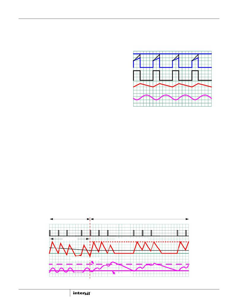
�Figure� 43� shows� the� typical� operating� waveforms� during� the� PWM�
�operation.� The� dotted� lines� illustrate� the� sum� of� the� compensation�
�ramp� and� the� current-sense� amplifier� CSA-output.�
�The� output� voltage� is� regulated� by� controlling� the� reference�
�voltage� to� the� current� loop.� The� bandgap� circuit� outputs� a� 0.6V�
�reference� voltage� to� the� voltage� control� loop.� The� feedback� signal�
�comes� from� the� V� FB� pin.� The� soft-start� block� only� affects� the�
�PWM�
�CLOCK�
�8� CYCLES�
�I� L�
�0�
�operation� during� the� start-up� and� will� be� discussed� separately�
�shortly.� The� error� amplifier� is� a� transconductance� amplifier� that�
�converts� the� voltage� error� signal� to� a� current� output.� The� voltage�
�loop� is� internally� compensated� with� the� 27pF� and� 200k� ?� RC�
�network.� The� maximum� EAMP� voltage� output� is� precisely�
�clamped� to� 0.8V.�
�V� EAMP�
�V� CSA�
�DUTY�
�CYCLE�
�I� L�
�V� OUT�
�FIGURE� 43.� PWM� OPERATION� WAVEFORMS�
�SKIP� Mode�
�Pulling� the� SYNC� pin� HIGH� (>2.0V)� forces� the� converter� into� PFM�
�mode.� The� ISL78228� enters� a� pulse-skipping� mode� at� light� load�
�to� minimize� the� switching� loss� by� reducing� the� switching�
�frequency.� Figure� 44� illustrates� the� skip-mode� operation.� A�
�zero-cross� sensing� circuit� shown� in� the� “Block� Diagram”� on�
�page� 13� monitors� the� N-MOSFET� current� for� zero� crossing.� When�
�8� consecutive� cycles� of� the� N-MOSFET� crossing� zero� are� detected,�
�the� regulator� enters� the� skip� mode.� During� the� 8� detecting� cycles,�
�the� current� in� the� inductor� is� allowed� to� become� negative.� The�
�counter� is� reset� to� zero� when� the� current� in� any� cycle� does� not�
�cross� zero.�
�Once� the� skip� mode� is� entered,� the� pulse� modulation� starts� being�
�controlled� by� the� SKIP� comparator� shown� in� the� “Block� Diagram”�
�on� page� 13.� Each� pulse� cycle� is� still� synchronized� by� the� PWM�
�clock.� The� P-MOSFET� is� turned� on� at� the� clock� and� turned� off�
�when� its� current� reaches� the� threshold� of� 250mA.� As� the� average�
�inductor� current� in� each� cycle� is� higher� than� the� average� current�
�of� the� load,� the� output� voltage� rises� cycle� over� cycle.� When� the�
�output� voltage� reaches� 1.5%� above� the� nominal� voltage,� the�
�PFM�
�PFM� CURRENT� LIMIT�
�LOAD� CURRENT�
�NOMINAL� +1.5%�
�V� OUT�
�NOMINAL�
�FIGURE� 44.� SKIP� MODE� OPERATION� WAVEFORMS�
�14�
�FN7849.2�
�December� 4,� 2013�
�相关PDF资料 |
PDF描述 |
|---|---|
| ISL6328IRZ-T | IC CTRLR PWM SYNC BUCK DL 48QFN |
| LB16WGW01 | SWITCH PUSHBUTTON SPDT 3A 125V |
| ISL6328CRZ-T | IC CTRLR PWM SYNC BUCK DL 48QFN |
| LB16WKW01 | SWITCH PUSHBUTTON SPDT 3A 125V |
| X9315WMIZ-2.7T1R5419 | IC DGTL POT 32POS 10K 8MSOP |
相关代理商/技术参数 |
参数描述 |
|---|---|
| ISL78233ARZ | 制造商:Intersil Corporation 功能描述:IC REG BUCK SYNC ADJ 3A 16QFN |
| ISL78233ARZ-T | 制造商:Intersil Corporation 功能描述:ISL78233ARZ AUTOMOTIVE 4A COMPACT SYNCHRONOUS BUCK REGULATOR - Tape and Reel |
| ISL78301 | 制造商:INTERSIL 制造商全称:Intersil Corporation 功能描述:40V, Low Quiescent Current, 150mA Linear Regulator for Automotive Applications |
| ISL78301FVEAZ | 功能描述:IC REG LDO 3.3V .15A 14HTSSOP RoHS:是 类别:集成电路 (IC) >> PMIC - 稳压器 - 线性 系列:- 产品培训模块:Lead (SnPb) Finish for COTS Obsolescence Mitigation Program 标准包装:2,500 系列:- 稳压器拓扑结构:正,固定式或可调式 输出电压:3.3V,2.5 V ~ 11 V 输入电压:6.5 V ~ 45 V 电压 - 压降(标准):0.9V @ 400mA 稳压器数量:1 电流 - 输出:400mA(最小) 电流 - 限制(最小):- 工作温度:-40°C ~ 125°C 安装类型:表面贴装 封装/外壳:16-WQFN 裸露焊盘 供应商设备封装:16-TQFN-EP(5x5) 包装:带卷 (TR) |
| ISL78301FVEAZ-T | 功能描述:IC REG LDO 3.3V .15A 14HTSSOP RoHS:是 类别:集成电路 (IC) >> PMIC - 稳压器 - 线性 系列:- 标准包装:2,000 系列:- 稳压器拓扑结构:正,可调式 输出电压:1.2 V ~ 5 V 输入电压:2.5 V ~ 7 V 电压 - 压降(标准):0.24V @ 800mA 稳压器数量:1 电流 - 输出:800mA 电流 - 限制(最小):1.2A 工作温度:-40°C ~ 125°C 安装类型:表面贴装 封装/外壳:TO-261-5,TO-261AB 供应商设备封装:SOT-223-5 包装:带卷 (TR) 其它名称:*LP3964EMPX-ADJLP3964EMPX-ADJLP3964EMPX-ADJ-NDLP3964EMPX-ADJ/NOPBTR |
发布紧急采购,3分钟左右您将得到回复。