- 您现在的位置:买卖IC网 > PDF目录17321 > ISL95210EVAL1Z (Intersil)EVALUATION BOARD FOR ISL95210 PDF资料下载
参数资料
| 型号: | ISL95210EVAL1Z |
| 厂商: | Intersil |
| 文件页数: | 11/20页 |
| 文件大小: | 0K |
| 描述: | EVALUATION BOARD FOR ISL95210 |
| 标准包装: | 1 |
| 主要目的: | DC/DC,步降 |
| 输出及类型: | 1,非隔离 |
| 输出电压: | 1.2V |
| 电流 - 输出: | 10A |
| 输入电压: | 5V |
| 稳压器拓扑结构: | 降压 |
| 频率 - 开关: | 800kHz |
| 板类型: | 完全填充 |
| 已供物品: | 板,文档 |
| 已用 IC / 零件: | ISL95210 |
�� �
�
�ISL95210�
�Theory� of� Operation�
�The� following� sections� will� provide� a� detailed� description� of� the�
�inner� workings� of� the� ISL95210� 10A� integrated� FET� regulator.�
�Start� -Up�
�The� ISL95210� will� not� respond� to� any� logic� inputs� until� VCC� and�
�Output� Voltage� Programming�
�The� highly� integrated� nature� of� the� ISL95210� simplifies� design�
�and� reduces� component� count.� The� VSEL0� and� VSEL1� pins� are�
�3-state� logic� inputs� to� an� integrated� DAC� that� controls� the� output�
�voltage� set� point� as� prescribed� in� Table� 1.�
�TABLE� 1.� DAC� CONTROLLED� OUTPUT� VOLTAGE� SETTINGS�
�PVCC� are� above� the� power-on� reset� (POR)� level� as� described� in�
�the� “Electrical� Specifications”� table� on� page� 5.� Once� the� POR�
�condition� is� achieved,� the� ISL95210� will� then� acknowledge� the�
�states� of� its� logic� inputs.� If� the� EN� pin� is� pulled� above� the� rising�
�threshold,� the� regulator� is� commanded� on� and� the� soft-start�
�sequence� is� initiated.�
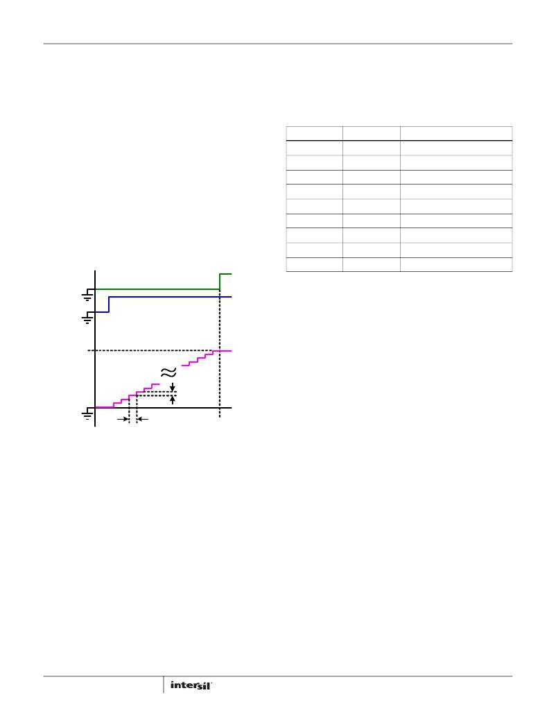
�During� soft-start,� the� programmed� output� voltage� set� point� is�
�determined� by� the� logic� states� of� VSEL0,� VSEL1,� MPCT� and� MSEL.�
�The� output� then� ramps� digitally� to� the� regulation� voltage� in�
�2.5mV/μs� steps.� Once� the� output� voltage� achieves� regulation,�
�the� power-good� monitor� output� (PGOOD)� is� toggled� high� to� the�
�voltage� provided� on� the� PG_IN� pin.� Figure� 25� illustrates� the� ideal�
�soft-start� behavior.�
�VSEL1�
�0�
�0�
�0�
�FLOAT�
�FLOAT�
�FLOAT�
�1�
�1�
�1�
�VSEL0�
�0�
�FLOAT�
�1�
�0�
�FLOAT�
�1�
�0�
�FLOAT�
�1�
�VOUT� (V)�
�0.600�
�0.750�
�0.900�
�1.000�
�1.050�
�1.100�
�1.200�
�1.500�
�1.800�
�EN�
�DAC� Voltage�
�PGOOD�
�PG_OUT�
�EN�
�DAC� VOLTAGE�
�NOTE:� 1� =� Input� High,� 0� =� Input� Low,� FLOAT� =� Input� unconnected� or� high-Z�
�(see� “Electrical� Specifications”� table� for� details).�
�This� allows� the� user� to� program� the� output� voltage� without� the�
�use� of� a� resistor� divider� network.� However,� if� the� user� wishes� to�
�program� values� of� VOUT� away� from� the� DAC� values,� a� resistor�
�divider� can� be� used.� However,� because� the� input� impedance� of�
�the� VOUT� pin� is� relatively� low,� the� top� resistor� in� the� divider� stack�
�(R1� in� Figure� 31)� must� be� kept� small� to� minimize� regulation� error�
�as� the� internal� resistance� changes� over-temperature� and� process�
�tolerances.� A� 100� Ω� resistor� is� recommended.� The� bottom�
�2.5mV�
�VOUT�
�2.5mV�
�resistor� in� the� divider� stack� (R2� in� Figure� 31)� can� be� derived� from�
�Equation� 3:�
�1us�
�t� SS�
�R1� ?� V� DAC�
�V� OUT� +� ?� ---------------� ?� –� ?� ---------------------------� ?� ?� V� DAC�
�1μs�
�t� SS�
�R2� =� -------------------------------------------------------------------------------------------------------�
�2� ?� R1� 205k� +� R� 1�
�?� 205k� ?� ?� 205k� ?�
�(EQ.� 3)�
�V� DAC�
�t� SS� =� ------------------�
�FIGURE� 25.� IDEALIZED� SOFT-START� WAVEFORM�
�Using� the� values� in� Tables� 1� and� 2,� the� soft-start� interval� can� be�
�easily� calculated� by� Equation� 1.�
�(EQ.� 1)�
�0.0025�
�The� units� of� Equation� 1� are� in� microseconds.� For� example:�
�-� VDAC� =� 1.200V�
�-� t� SS� =� 1.200V� /� 0.0025� =� 480μs�
�The� fixed� soft-start� slew� rate� of� 2.5mV/μs� allows� for� easy�
�calculation� of� the� in-rush� current.�
�For� example:�
�-� Desired� VOUT� =� 1.35V�
�-� VDAC� =� 1.32V� (1.2V� +10%� margin)�
�-� R1� =� 100� Ω�
�-� R2� =� 4.351k� Ω� (select� nearest� standard� value)�
�NOTE:� The� resistor� divider� should� not� be� used� to� program� VOUT�
�more� than� 5%� away� from� any� preset� DAC� value.� If� this� limit� is�
�exceeded,� the� modulator� will� be� severely� imbalanced� and� may�
�result� in� loop� instability� and� regulator� shutdown.�
�The� use� of� a� resistor� network� also� limits� the� soft� discharge�
�I� INRUSH� =� (� 2500� ?� C� OUT� )�
�(EQ.� 2)�
�feature� of� the� ISL95210.� More� detail� on� this� operation� can� be�
��Consequently,� the� in-rush� is� manageable� for� all� practical� values�
�of� output� capacitance.� For� example:�
�-� COUT� =� 330μF�
�-� Inrush� Current� =� 2500*330μF� =� 0.825A�
�11�
�In� addition� to� digitally� controlled� output� voltage� programming,�
�the� ISL95210� includes� the� ability� to� margin� the� output� voltage� up�
�and� down� from� the� set� point� for� use� in� end-of-line� manufacturing�
�reliability� tests.� The� MPCT� pin� controls� the� amount� of� margining�
�desired� by� the� user� and� the� MSEL� pin� determines� when�
�margining� is� engaged.� In� all� margining� conditions,� the� output�
�voltage� is� slewed� to� the� new� value� at� the� soft-start� rate� of�
�FN6938.4�
�December� 15,� 2011�
�相关PDF资料 |
PDF描述 |
|---|---|
| EBC18DRTN | CONN EDGECARD 36POS DIP .100 SLD |
| EEC20DRTI | CONN EDGECARD 40POS DIP .100 SLD |
| ECC08DRTI | CONN EDGECARD 16POS DIP .100 SLD |
| EBC17DREN | CONN EDGECARD 34POS .100 EYELET |
| GEM12DRKF-S13 | CONN EDGECARD 24POS .156 EXTEND |
相关代理商/技术参数 |
参数描述 |
|---|---|
| ISL95210HRZ | 功能描述:直流/直流开关调节器 ISL95210 5V/10ABUCK IGRATE FET NTBOOK RoHS:否 制造商:International Rectifier 最大输入电压:21 V 开关频率:1.5 MHz 输出电压:0.5 V to 0.86 V 输出电流:4 A 输出端数量: 最大工作温度: 安装风格:SMD/SMT 封装 / 箱体:PQFN 4 x 5 |
| ISL95210HRZ-T | 功能描述:直流/直流开关调节器 ISL95210 5V/10ABUCK IGRATE FET NTBOOK RoHS:否 制造商:International Rectifier 最大输入电压:21 V 开关频率:1.5 MHz 输出电压:0.5 V to 0.86 V 输出电流:4 A 输出端数量: 最大工作温度: 安装风格:SMD/SMT 封装 / 箱体:PQFN 4 x 5 |
| ISL95210HRZ-T7A | 功能描述:直流/直流开关调节器 ISL95210 5V/10ABUCK IGRATE FET NTBOOK RoHS:否 制造商:International Rectifier 最大输入电压:21 V 开关频率:1.5 MHz 输出电压:0.5 V to 0.86 V 输出电流:4 A 输出端数量: 最大工作温度: 安装风格:SMD/SMT 封装 / 箱体:PQFN 4 x 5 |
| ISL95210IRZ | 功能描述:直流/直流开关调节器 ISL95210 5V/10ABUCK IGRATE FET INDUST RoHS:否 制造商:International Rectifier 最大输入电压:21 V 开关频率:1.5 MHz 输出电压:0.5 V to 0.86 V 输出电流:4 A 输出端数量: 最大工作温度: 安装风格:SMD/SMT 封装 / 箱体:PQFN 4 x 5 |
| ISL95210IRZ-T | 功能描述:直流/直流开关调节器 ISL95210 5V/10ABUCK IGRATE FET NTBOOK RoHS:否 制造商:International Rectifier 最大输入电压:21 V 开关频率:1.5 MHz 输出电压:0.5 V to 0.86 V 输出电流:4 A 输出端数量: 最大工作温度: 安装风格:SMD/SMT 封装 / 箱体:PQFN 4 x 5 |
发布紧急采购,3分钟左右您将得到回复。