- 您现在的位置:买卖IC网 > PDF目录17331 > ISL97646IRZ-EVALZ (Intersil)BOARD EVALUATION FOR ISL97646 PDF资料下载
参数资料
| 型号: | ISL97646IRZ-EVALZ |
| 厂商: | Intersil |
| 文件页数: | 10/15页 |
| 文件大小: | 0K |
| 描述: | BOARD EVALUATION FOR ISL97646 |
| 标准包装: | 1 |
| 主要目的: | DC/DC,LDO 步升 |
| 输出及类型: | 2,非隔离 |
| 电流 - 输出: | 350mA |
| 输入电压: | 2.7 ~ 5.5 V |
| 稳压器拓扑结构: | 升压 |
| 频率 - 开关: | 650kHz,1.2MHz |
| 板类型: | 完全填充 |
| 已供物品: | 板 |
| 已用 IC / 零件: | ISL97646 |
�� �
�
�ISL97646�
�Operation�
�The� boost� converter� is� a� current� mode� PWM� converter�
�operating� at� either� a� 650kHz� or� 1.2MHz.� It� can� operate� in�
�The� current� through� the� MOSFET� is� limited� to� 2.6A� PEAK� .�
�This� restricts� the� maximum� output� current� (average)� based�
�on� the� Equation� 3:�
�I� OMAX� =� ?� I� LMT� –� --------� ?� ×� ---------�
�V� O�
�both� discontinuous� conduction� mode� (DCM)� at� light� load� and�
�continuous� mode� (CCM).� In� continuous� current� mode,�
�current� flows� continuously� in� the� inductor� during� the� entire�
�switching� cycle� in� steady� state� operation.� The� voltage�
�?� 2� ?�
�Δ� I� L� V� IN�
�(EQ.� 3)�
�conversion� ratio� in� continuous� current� mode� is� given� by:�
�Where� Δ� I� L� is� peak� to� peak� inductor� ripple� current,� and� is� set�
�V� BOOST� 1�
�V� IN�
�Δ� I� L� =� ---------� ×� ----�
�f� s�
�------------------------� =� -------------�
�1� –� D�
�(EQ.� 1)�
�by:�
�V� IN� D�
�L�
�(EQ.� 4)�
�Where� D� is� the� duty� cycle� of� the� switching� MOSFET.�
�Figure� 13� shows� the� block� diagram� of� the� boost� regulator.� It�
�uses� a� summing� amplifier� architecture� consisting� of� gm�
�stages� for� voltage� feedback,� current� feedback� and� slope�
�compensation.� A� comparator� looks� at� the� peak� inductor�
�current� cycle� by� cycle� and� terminates� the� PWM� cycle� if� the�
�current� limit� is� reached.�
�An� external� resistor� divider� is� required� to� divide� the� output�
�voltage� down� to� the� nominal� reference� voltage.� Current�
�drawn� by� the� resistor� network� should� be� limited� to� maintain�
�the� overall� converter� efficiency.� The� maximum� value� of� the�
�resistor� network� is� limited� by� the� feedback� input� bias� current�
�and� the� potential� for� noise� being� coupled� into� the� feedback�
�pin.� A� resistor� network� in� the� order� of� 60k� Ω� is� recommended.�
�where� f� S� is� the� switching� frequency� (650kHz� or� 1.2MHz).�
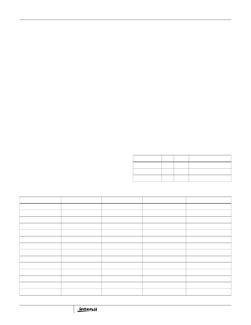
�Table� 2� gives� typical� values� (margins� are� considered� 10%,�
�3%,� 20%,� 10%� and� 15%� on� V� IN� ,� V� O� ,� L,� f� S� and� I� OMAX� ).�
�Capacitor�
�An� input� capacitor� is� used� to� suppress� the� voltage� ripple�
�injected� into� the� boost� converter.� The� ceramic� capacitor� with�
�capacitance� larger� than� 10μF� is� recommended.� The� voltage�
�rating� of� input� capacitor� should� be� larger� than� the� maximum�
�input� voltage.� Some� capacitors� are� recommended� in� Table� 1�
�for� input� capacitor.�
�TABLE� 1.� BOOST� CONVERTER� INPUT� CAPACITOR�
�RECOMMENDATION�
�The� boost� converter� output� voltage� is� determined� by�
�Equation� 2:�
�CAPACITOR�
�10μF/16V�
�SIZE�
�1206�
�MFG�
�TDK�
�PART� NUMBER�
�C3216X7R1C106M�
�V� BOOST� =� ---------------------� � V� FB�
�R� 1� +� R� 2�
�R� 2�
�(EQ.� 2)�
�10μF/10V�
�22μF/10V�
�0805�
�1210�
�Murata�
�Murata�
�GRM21BR61A106K�
�GRB32ER61A226K�
�TABLE� 2.� MAXIMUM� OUTPUT� CURRENT� CALCULATION�
�V� IN� (V)�
�3�
�3�
�3�
�5�
�5�
�5�
�5�
�3�
�3�
�3�
�5�
�5�
�5�
�5�
�V� O� (V)�
�9�
�12�
�15�
�9�
�12�
�15�
�18�
�9�
�12�
�15�
�9�
�12�
�15�
�18�
�L� (μH)�
�10�
�10�
�10�
�10�
�10�
�10�
�10�
�10�
�10�
�10�
�10�
�10�
�10�
�10�
�f� s� (MHz)�
�0.65�
�0.65�
�0.65�
�0.65�
�0.65�
�0.65�
�0.65�
�1.2�
�1.2�
�1.2�
�1.2�
�1.2�
�1.2�
�1.2�
�I� OMAX� (mA)�
�636�
�419�
�289�
�1060�
�699�
�482�
�338�
�742�
�525�
�395�
�1236�
�875�
�658�
�514�
�10�
�FN6265.1�
�December� 14,� 2007�
�相关PDF资料 |
PDF描述 |
|---|---|
| RBC17DRYH | CONN EDGECARD 34POS DIP .100 SLD |
| 195D475X9015E2T | CAP TANT 4.7UF 15V 10% 2208 |
| IR3312 | IC SWITCH HI-SIDE 1CH TO-220-5 |
| 195D475X0015E2T | CAP TANT 4.7UF 15V 20% 2208 |
| A9BBA-0804E | FLEX CABLE - AFJ08A/AE08/AFJ08A |
相关代理商/技术参数 |
参数描述 |
|---|---|
| ISL97646IRZ-T | 功能描述:直流/直流开关调节器 ISL97646IRZOOST +L DO +VON SLICE +VCOM RoHS:否 制造商:International Rectifier 最大输入电压:21 V 开关频率:1.5 MHz 输出电压:0.5 V to 0.86 V 输出电流:4 A 输出端数量: 最大工作温度: 安装风格:SMD/SMT 封装 / 箱体:PQFN 4 x 5 |
| ISL97646IRZ-TK | 功能描述:直流/直流开关调节器 ISL97646IRZOOST +L DO +VON SLICE +VCOM RoHS:否 制造商:International Rectifier 最大输入电压:21 V 开关频率:1.5 MHz 输出电压:0.5 V to 0.86 V 输出电流:4 A 输出端数量: 最大工作温度: 安装风格:SMD/SMT 封装 / 箱体:PQFN 4 x 5 |
| ISL97648IRTZ | 功能描述:IC BOOST DC/DC REG RoHS:是 类别:集成电路 (IC) >> PMIC - 稳压器 - 专用型 系列:- 标准包装:2,000 系列:- 应用:控制器,DSP 输入电压:4.5 V ~ 25 V 输出数:2 输出电压:最低可调至 1.2V 工作温度:-40°C ~ 85°C 安装类型:表面贴装 封装/外壳:30-TFSOP(0.173",4.40mm 宽) 供应商设备封装:30-TSSOP 包装:带卷 (TR) |
| ISL97648IRTZ-T | 制造商:Intersil Corporation 功能描述:HIGH VOLTAGE TFT-LCD LOGIC DRIVER (56 LD TQFN 8X8) - Tape and Reel |
| ISL97648IRTZ-TK | 制造商:Intersil Corporation 功能描述:HIGH VOLTAGE TFT-LCD LOGIC DRIVER (56 LD TQFN 8X8) - Tape and Reel |
发布紧急采购,3分钟左右您将得到回复。