- 您现在的位置:买卖IC网 > PDF目录20789 > ISL97672AIRZ-T (Intersil)IC LED DRVR LOW DIMMING 20QFN PDF资料下载
参数资料
| 型号: | ISL97672AIRZ-T |
| 厂商: | Intersil |
| 文件页数: | 13/16页 |
| 文件大小: | 0K |
| 描述: | IC LED DRVR LOW DIMMING 20QFN |
| 标准包装: | 6,000 |
| 拓扑: | PWM,升压(升压) |
| 输出数: | 6 |
| 内部驱动器: | 是 |
| 类型 - 主要: | 背光 |
| 频率: | 200kHz ~ 1.5MHz |
| 电源电压: | 4.5 V ~ 26.5 V |
| 输出电压: | 45V |
| 安装类型: | 表面贴装 |
| 封装/外壳: | 20-VFQFN 裸露焊盘 |
| 供应商设备封装: | 20-QFN(3x4) |
| 包装: | 带卷 (TR) |
| 工作温度: | -40°C ~ 85°C |
�� �
�
�ISL97672A�
�Input� Capacitor�
�Switching� regulators� require� input� capacitors� to� deliver� peak�
�charging� current� and� to� reduce� the� impedance� of� the� input�
�supply.� The� capacitors� reduce� interaction� between� the� regulator�
�and� input� supply,� thus� improving� system� stability.� The� high�
�switching� frequency� of� the� loop� causes� almost� all� ripple� current�
�to� flow� into� the� input� capacitor,� which� must� be� rated� accordingly.�
�A� capacitor� with� low� internal� series� resistance� should� be� chosen�
�to� minimize� heating� effects� and� to� improve� system� efficiency.�
�The� X5R� and� X7R� ceramic� capacitors� offer� small� size� and� a� lower�
�value� for� temperature� and� voltage� coefficient� compared� to� other�
�ceramic� capacitors.�
�An� input� capacitor� of� 10μF� is� recommended.� Ensure� that� the�
�voltage� rating� of� the� input� capacitor� is� able� to� handle� the� full�
�supply� range.�
�Inductor�
�Inductor� selection� should� be� based� on� its� maximum� current� (I� SAT� )�
�characteristics,� power� dissipation� (DCR),� EMI� susceptibility�
�(shielded� vs� unshielded),� and� size.� Inductor� type� and� value�
�influence� many� key� parameters,� including� ripple� current,� current�
�limit,� efficiency,� transient� performance,� and� stability.�
�Inductor� maximum� current� capability� must� be� adequate� to�
�handle� the� peak� current� in� the� worst-case� condition.� If� an�
�inductor� core� with� too� low� a� current� rating� is� chosen,� saturation�
�in� the� core� will� cause� the� effective� inductor� value� to� fall,� leading�
�to� an� increase� in� peak-to-average� current� level,� poor� efficiency,�
�and� overheating� in� the� core.� The� series� resistance,� DCR,� within�
�the� inductor� causes� conduction� loss� and� heat� dissipation.� A�
�shielded� inductor� is� usually� more� suitable� for� EMI-susceptible�
�applications� such� as� LED� backlighting.�
�The� peak� current� can� be� derived� from� the� voltage� across� the�
�inductor� during� the� Off� period,� as� shown� in� Equation� 10:�
�IL� peak� =� (� V� O� ×� I� O� )� ?� (� 85%� ×� V� I� )� +� 1� ?� 2� [� V� I� ×� (� V� O� –� V� I� )� ?� (� L� ×� V� O� ×� f� S� )� ]�
�(EQ.� 10)�
�The� value� of� 85%� is� an� average� term� for� the� efficiency�
�approximation.� The� first� term� is� average� current� that� is� inversely�
�proportional� to� the� input� voltage.� The� second� term� is� inductor�
�current� change� that� is� inversely� proportional� to� L� and� f� S� .� As� a�
�result,� for� a� given� switching� frequency� and� minimum� input�
�voltage� at� which� the� system� operates,� the� inductor� I� SAT� must� be�
�chosen� carefully.�
�Output� Capacitors�
�The� output� capacitor� smooths� the� output� voltage� and� supplies�
�load� current� directly� during� the� conduction� phase� of� the� power�
�switch.� Output� ripple� voltage� consists� of� discharge� and� charge� of�
�the� output� capacitor� during� FET� On� and� OFF� time� and� the� voltage�
�drop� due� to� flow� through� the� ESR� of� the� output� capacitor.� The�
�ripple� voltage� can� be� shown� as� Equation� 11:�
�user� must� select� an� output� capacitor� with� low� ESR� and� adequate�
�input� ripple� current� capability.�
�Note:� Capacitors� have� a� voltage� coefficient� that� makes� their�
�effective� capacitance� drop� as� the� voltage� across� them� increases.�
�C� OUT� in� Equation� 11� assumes� the� effective� value� of� the� capacitor�
�at� a� particular� voltage� and� not� the� manufacturer’s� stated� value,�
�measured� at� 0V.�
�The� value� of� Δ� V� Co� can� be� reduced� by� increasing� C� O� or� f� S� ,� or� by�
�using� small� ESR� capacitors.� In� general,� ceramic� capacitors� are�
�the� best� choice� for� output� capacitors� in� small-� to� medium-sized�
�LCD� backlight� applications,� due� to� their� cost,� form� factor,� and� low�
�ESR.�
�A� larger� output� capacitor� also� eases� driver� response� during� the�
�PWM� dimming� Off� period,� due� to� the� longer� sample� and� hold�
�effect� of� the� output� drooping.� The� driver� does� not� need� to� boost�
�harder� in� the� next� On� period� that� minimizes� transient� current.�
�The� output� capacitor� is� also� needed� for� compensation,� and� in�
�general,� 2x4.7μF/50V� ceramic� capacitors� are� suitable� for�
�notebook� display� backlight� applications.�
�Schottky� Diode�
�A� high-speed� rectifier� diode� is� necessary� to� prevent� excessive�
�voltage� overshoot.� Schottky� diodes� are� recommended� because�
�of� their� fast� recovery� time,� low� forward� voltage� and� reverse�
�leakage� current,� which� minimize� losses.� The� reverse� voltage�
�rating� of� the� selected� Schottky� diode� must� be� higher� than� the�
�maximum� output� voltage.� Also� the� average/peak� current� rating�
�of� the� Schottky� diode� must� meet� the� output� current� and� peak�
�inductor� current� requirements.�
�Applications�
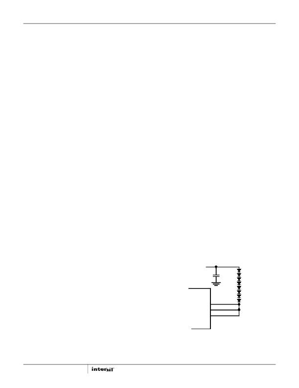
�High-Current� Applications�
�Each� channel� of� the� ISL97672A� can� support� up� to� 30mA�
�(50mA� @� V� IN� =� 12V).� For� applications� that� need� higher� current,�
�multiple� channels� can� be� grouped� to� achieve� the� desired� current�
�(Figure� 21).� For� example,� the� cathode� of� the� last� LED� can� be�
�connected� to� CH0� through� CH2;� this� configuration� can� be� treated�
�as� a� single� string� with� 90mA� current� driving� capability.�
�V� OUT�
�CH0�
�CH1�
�CH2�
�Δ� V� CO� =� (� I� O� ?� C� O� ×� D� ?� f� S� )� +� (� (� I� O� ×� ESR� )�
�(EQ.� 11)�
�The� conservation� of� charge� principle� shown� in� Equation� 9� also�
�indicates� that,� during� the� boost� switch� Off� period,� the� output�
�capacitor� is� charged� with� the� inductor� ripple� current,� minus� a�
�relatively� small� output� current� in� boost� topology.� As� a� result,� the�
�13�
�FIGURE� 21.� GROUPING� MULTIPLE� CHANNELS� FOR� HIGH� CURRENT�
�APPLICATIONS�
�FN7710.3�
�November� 22,� 2013�
�相关PDF资料 |
PDF描述 |
|---|---|
| JWS7515/A | PWR SUP 15.0V 5A SNG OUTPUT |
| JWS7548/A | POWER SUPL 75W 48V 1.6A ENCLOSED |
| USR 2-0808 14K OHM D 0.01% 1PPM | RES 14K OHM .6W .01% FOIL RADIAL |
| USR 2-0808 12K OHM D 0.01% 1PPM | RES 12K OHM .6W .01% FOIL RADIAL |
| USR 2-T220B 22000.00 OHM D 0.1% 3PPM | RES 22K OHM 6W .1% FOIL TO-220 |
相关代理商/技术参数 |
参数描述 |
|---|---|
| ISL97672AIRZ-TK | 功能描述:IC LED DRVR LOW DIMMING 20QFN RoHS:是 类别:集成电路 (IC) >> PMIC - LED 驱动器 系列:- 产品培训模块:Lead (SnPb) Finish for COTS Obsolescence Mitigation Program 标准包装:2,500 系列:- 恒定电流:- 恒定电压:- 拓扑:升压(升压),切换式电容器(充电泵) 输出数:1 内部驱动器:是 类型 - 主要:背光 类型 - 次要:白色 LED 频率:625kHz ~ 875kHz 电源电压:2.7 V ~ 5.3 V 输出电压:5V 安装类型:表面贴装 封装/外壳:10-TFSOP,10-MSOP(0.118",3.00mm 宽) 供应商设备封装:10-µMAX 包装:带卷 (TR) 工作温度:-40°C ~ 85°C |
| ISL97672BIRZ | 功能描述:IC LED DRVR BACKLIGHT 20QFN RoHS:是 类别:集成电路 (IC) >> PMIC - LED 驱动器 系列:- 产品培训模块:Lead (SnPb) Finish for COTS Obsolescence Mitigation Program 标准包装:2,500 系列:- 恒定电流:- 恒定电压:- 拓扑:升压(升压),切换式电容器(充电泵) 输出数:1 内部驱动器:是 类型 - 主要:背光 类型 - 次要:白色 LED 频率:625kHz ~ 875kHz 电源电压:2.7 V ~ 5.3 V 输出电压:5V 安装类型:表面贴装 封装/外壳:10-TFSOP,10-MSOP(0.118",3.00mm 宽) 供应商设备封装:10-µMAX 包装:带卷 (TR) 工作温度:-40°C ~ 85°C |
| ISL97672BIRZ-T | 功能描述:IC LED DRVR BACKLIGHT 20QFN RoHS:是 类别:集成电路 (IC) >> PMIC - LED 驱动器 系列:- 产品培训模块:Lead (SnPb) Finish for COTS Obsolescence Mitigation Program 标准包装:2,500 系列:- 恒定电流:- 恒定电压:- 拓扑:升压(升压),切换式电容器(充电泵) 输出数:1 内部驱动器:是 类型 - 主要:背光 类型 - 次要:白色 LED 频率:625kHz ~ 875kHz 电源电压:2.7 V ~ 5.3 V 输出电压:5V 安装类型:表面贴装 封装/外壳:10-TFSOP,10-MSOP(0.118",3.00mm 宽) 供应商设备封装:10-µMAX 包装:带卷 (TR) 工作温度:-40°C ~ 85°C |
| ISL97672IRZ | 制造商:Intersil Corporation 功能描述:6-CH LED DRIVER WITH PWM DIMMING - Rail/Tube 制造商:Intersil 功能描述:6-CH LED DRVR W/PWM DIM |
| ISL97672IRZ-T | 制造商:Intersil Corporation 功能描述:6-CH LED DRIVER WITH PWM DIMMING, T&R - Tape and Reel 制造商:Intersil 功能描述:6-CH LED DRVR W/PWM DIM |
发布紧急采购,3分钟左右您将得到回复。