- 您现在的位置:买卖IC网 > PDF目录261242 > IT80C52XXX-12D (TEMIC SEMICONDUCTORS) 8-BIT, MROM, 12 MHz, MICROCONTROLLER, PQFP44 PDF资料下载
参数资料
| 型号: | IT80C52XXX-12D |
| 厂商: | TEMIC SEMICONDUCTORS |
| 元件分类: | 微控制器/微处理器 |
| 英文描述: | 8-BIT, MROM, 12 MHz, MICROCONTROLLER, PQFP44 |
| 文件页数: | 26/32页 |
| 文件大小: | 3152K |
| 代理商: | IT80C52XXX-12D |
第1页第2页第3页第4页第5页第6页第7页第8页第9页第10页第11页第12页第13页第14页第15页第16页第17页第18页第19页第20页第21页第22页第23页第24页第25页当前第26页第27页第28页第29页第30页第31页第32页
84
Atmel ATmega16/32/64/M1/C1 [DATASHEET]
7647K–AVR–12/13
A frequency (with 50% duty cycle) waveform output in fast PWM mode can be achieved by setting OC0x to toggle its logical
level on each compare match (COM0x1:0 = 1). The waveform generated will have a maximum frequency of fOC0 = fclk_I/O/2 when
OCR0A is set to zero. This feature is similar to the OC0A toggle in CTC mode, except the double buffer feature of the output
compare unit is enabled in the fast PWM mode.
12.6.4 Phase Correct PWM Mode
The phase correct PWM mode (WGM02:0 = 1 or 5) provides a high resolution phase correct PWM waveform generation option.
The phase correct PWM mode is based on a dual-slope operation. The counter counts repeatedly from BOTTOM to TOP and
then from TOP to BOTTOM. TOP is defined as 0xFF when WGM2:0 = 1, and OCR0A when WGM2:0 = 5. In non-inverting
Compare Output mode, the Output Compare (OC0x) is cleared on the compare match between TCNT0 and OCR0x while
upcounting, and set on the compare match while downcounting. In inverting output compare mode, the operation is inverted.
The dual-slope operation has lower maximum operation frequency than single slope operation. However, due to the symmetric
feature of the dual-slope PWM modes, these modes are preferred for motor control applications.
In phase correct PWM mode the counter is incremented until the counter value matches TOP. When the counter reaches TOP,
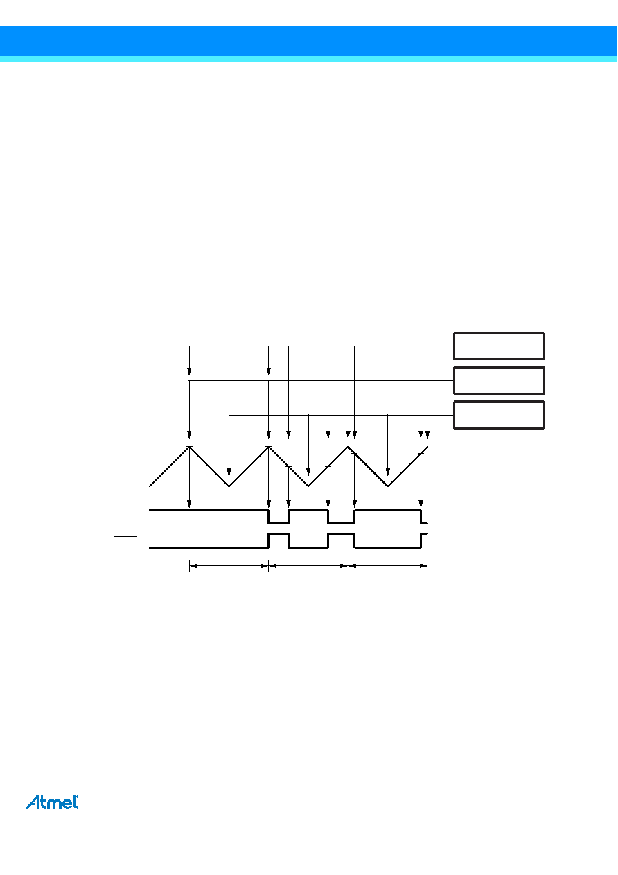
it changes the count direction. The TCNT0 value will be equal to TOP for one timer clock cycle. The timing diagram for the
phase correct PWM mode is shown on Figure 12-7. The TCNT0 value is in the timing diagram shown as a histogram for
illustrating the dual-slope operation. The diagram includes non-inverted and inverted PWM outputs. The small horizontal line
marks on the TCNT0 slopes represent compare matches between OCR0x and TCNT0.
Figure 12-7. Phase Correct PWM Mode, Timing Diagram
The Timer/Counter overflow flag (TOV0) is set each time the counter reaches BOTTOM. The interrupt flag can be used to
generate an interrupt each time the counter reaches the BOTTOM value.
In phase correct PWM mode, the compare unit allows generation of PWM waveforms on the OC0x pins. Setting the COM0x1:0
bits to two will produce a non-inverted PWM. An inverted PWM output can be generated by setting the COM0x1:0 to three:
Setting the COM0A0 bits to one allows the OC0A pin to toggle on compare matches if the WGM02 bit is set. This option is not
available for the OC0B pin (see Table 12-7 on page 88). The actual OC0x value will only be visible on the port pin if the data
direction for the port pin is set as output. The PWM waveform is generated by clearing (or setting) the OC0x register at the
compare match between OCR0x and TCNT0 when the counter increments, and setting (or clearing) the OC0x register at
compare match between OCR0x and TCNT0 when the counter decrements. The PWM frequency for the output when using
phase correct PWM can be calculated by the following equation:
The N variable represents the prescale factor (1, 8, 64, 256, or 1024).
123
TCNTn
(COMnx1:0 = 2)
(COMnx1:0 = 3)
OCnx
Period
TOVn Interrupt
Flag Set
OCRnx Update
OCnx Interrupt
Flag Set
f
OCnxPCPWM
f
clk_I/O
N 510
-----------------
=
相关PDF资料 |
PDF描述 |
|---|---|
| ID80C52TXXX-L16D | 8-BIT, MROM, 16 MHz, MICROCONTROLLER, CDIP40 |
| IT80C52XXX-20D | 8-BIT, MROM, 20 MHz, MICROCONTROLLER, PQFP44 |
| IV80C32XXX-36 | 8-BIT, 36 MHz, MICROCONTROLLER, PQFP44 |
| IF180C154-16D | 8-BIT, 16 MHz, MICROCONTROLLER, PQFP44 |
| IT83C154DCXXX-16 | 8-BIT, MROM, 16 MHz, MICROCONTROLLER, PQFP44 |
相关代理商/技术参数 |
参数描述 |
|---|---|
| IT80F | 制造商:未知厂家 制造商全称:未知厂家 功能描述:TRIAC|50V V(DRM)|8A I(T)RMS|TO-220 |
| IT80G | 制造商:未知厂家 制造商全称:未知厂家 功能描述:TRIAC|50V V(DRM)|8A I(T)RMS|TO-220 |
| IT810B | 制造商:未知厂家 制造商全称:未知厂家 功能描述:Analog IC |
| IT8152FG | 制造商:未知厂家 制造商全称:未知厂家 功能描述:Specification|Errata_v0.1 for it8152fg_v0.3.4 |
| IT8172G | 制造商:未知厂家 制造商全称:未知厂家 功能描述:RISC Companion Chip|Errata v0.2 for it8172g_v0.6 |
发布紧急采购,3分钟左右您将得到回复。