- 您现在的位置:买卖IC网 > PDF目录79616 > IV80C31-25R (ATMEL CORP) 8-BIT, 25 MHz, MICROCONTROLLER, PQFP44 PDF资料下载
参数资料
| 型号: | IV80C31-25R |
| 厂商: | ATMEL CORP |
| 元件分类: | 微控制器/微处理器 |
| 英文描述: | 8-BIT, 25 MHz, MICROCONTROLLER, PQFP44 |
| 封装: | 1.40 MM HEIGHT, QFP-44 |
| 文件页数: | 9/91页 |
| 文件大小: | 19688K |
| 代理商: | IV80C31-25R |
第1页第2页第3页第4页第5页第6页第7页第8页当前第9页第10页第11页第12页第13页第14页第15页第16页第17页第18页第19页第20页第21页第22页第23页第24页第25页第26页第27页第28页第29页第30页第31页第32页第33页第34页第35页第36页第37页第38页第39页第40页第41页第42页第43页第44页第45页第46页第47页第48页第49页第50页第51页第52页第53页第54页第55页第56页第57页第58页第59页第60页第61页第62页第63页第64页第65页第66页第67页第68页第69页第70页第71页第72页第73页第74页第75页第76页第77页第78页第79页第80页第81页第82页第83页第84页第85页第86页第87页第88页第89页第90页第91页
148
7679H–CAN–08/08
AT90CAN32/64/128
Depending on the mode of operation used, the counter is cleared, incremented, or decremented
at each timer clock (clk
T2). clkT2 can be generated from an external or internal clock source,
selected by the Clock Select bits (CS22:0). When no clock source is selected (CS22:0 = 0) the
timer is stopped. However, the TCNT2 value can be accessed by the CPU, regardless of
whether clk
T2 is present or not. A CPU write overrides (has priority over) all counter clear or
count operations.
The counting sequence is determined by the setting of the WGM21 and WGM20 bits located in
the Timer/Counter Control Register (TCCR2A). There are close connections between how the
counter behaves (counts) and how waveforms are generated on the Output Compare output
OC2A. For more details about advanced counting sequences and waveform generation, see
The Timer/Counter Overflow Flag (TOV2) is set according to the mode of operation selected by
the WGM21:0 bits. TOV2 can be used for generating a CPU interrupt.
14.5
Output Compare Unit
The 8-bit comparator continuously compares TCNT2 with the Output Compare Register
(OCR2A). Whenever TCNT2 equals OCR2A, the comparator signals a match. A match will set
the Output Compare Flag (OCF2A) at the next timer clock cycle. If enabled (OCIE2A = 1), the
Output Compare Flag generates an Output Compare interrupt. The OCF2A flag is automatically
cleared when the interrupt is executed. Alternatively, the OCF2A flag can be cleared by software
by writing a logical one to its I/O bit location. The Waveform Generator uses the match signal to
generate an output according to operating mode set by the WGM21:0 bits and Compare Output
mode (COM2A1:0) bits. The max and bottom signals are used by the Waveform Generator for
handling the special cases of the extreme values in some modes of operation (“Modes of Oper-
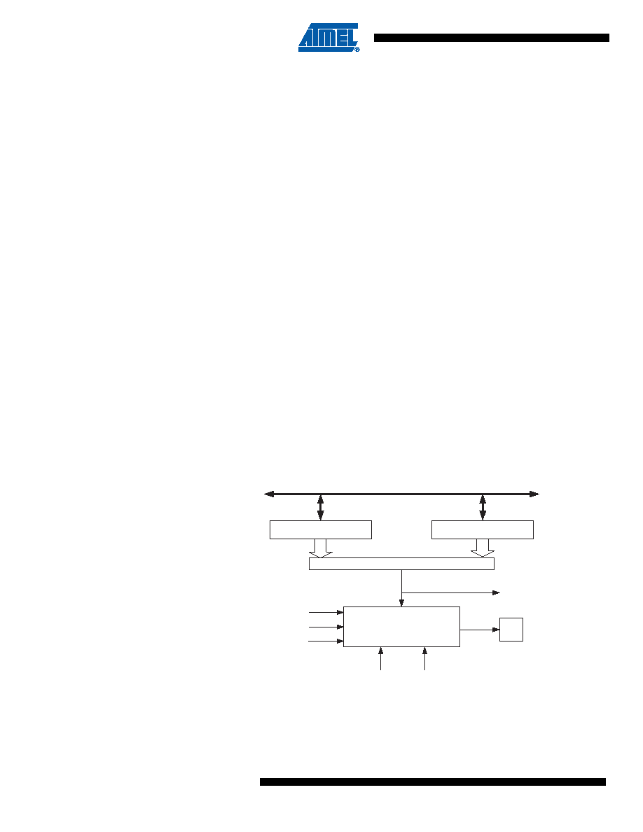
Figure 14-4 shows a block diagram of the Output Compare unit.
Figure 14-4. Output Compare Unit, Block Diagram
The OCR2A Register is double buffered when using any of the Pulse Width Modulation (PWM)
modes. For the Normal and Clear Timer on Compare (CTC) modes of operation, the double
buffering is disabled. The double buffering synchronizes the update of the OCR2A Compare
OCFnx (Int.Req.)
= (8-bit Comparator )
OCRnx
OCnx
DATA BUS
TCNTn
WGMn1:0
Waveform Generator
top
FOCn
COMnX1:0
bottom
相关PDF资料 |
PDF描述 |
|---|---|
| IT80C31-20R | 8-BIT, 20 MHz, MICROCONTROLLER, PQFP44 |
| IS80C51C-16R | 8-BIT, MROM, 16 MHz, MICROCONTROLLER, PQCC44 |
| IS80C51C-L16R | 8-BIT, MROM, 16 MHz, MICROCONTROLLER, PQCC44 |
| IF180C51C-12R | 8-BIT, MROM, 12 MHz, MICROCONTROLLER, PQFP44 |
| IF280C51C-12D | 8-BIT, MROM, 12 MHz, MICROCONTROLLER, PQFP44 |
相关代理商/技术参数 |
参数描述 |
|---|---|
| IV80C31-30 | 制造商:未知厂家 制造商全称:未知厂家 功能描述:8-Bit Microcontroller |
| IV80C31-36 | 制造商:未知厂家 制造商全称:未知厂家 功能描述:8-Bit Microcontroller |
| IV80C31-L16 | 制造商:未知厂家 制造商全称:未知厂家 功能描述:8-Bit Microcontroller |
| IV80C32-12 | 制造商:未知厂家 制造商全称:未知厂家 功能描述:8-Bit Microcontroller |
| IV80C32-12R | 制造商:未知厂家 制造商全称:未知厂家 功能描述:8-Bit Microcontroller |
发布紧急采购,3分钟左右您将得到回复。