- 您现在的位置:买卖IC网 > PDF目录262391 > KW025A0Y41-BZ 1-OUTPUT 45 W DC-DC REG PWR SUPPLY MODULE PDF资料下载
参数资料
| 型号: | KW025A0Y41-BZ |
| 元件分类: | 电源模块 |
| 英文描述: | 1-OUTPUT 45 W DC-DC REG PWR SUPPLY MODULE |
| 封装: | ROHS COMPLIANT |
| 文件页数: | 6/24页 |
| 文件大小: | 2376K |
| 代理商: | KW025A0Y41-BZ |
Preliminary Data Sheet
March 24, 2006
KW010/015/020/025 Series Power Modules:
36 – 75Vdc Input; 1.0 to 5.0Vdc Output; 10 to 25A Output current
Tyco Electronics Power Systems
14
Feature Descriptions (continued)
ΚΩ
=
22
.
10
8
511
down
trim
R
current-limiting circuitry and can endure current
limiting continuously. At the point of current-limit
inception, the unit enters hiccup mode. If the unit is
not configured with auto–restart, then it will latch off
following the over current condition. The module can
be restarted by cycling the dc input power for at least
one second or by toggling the remote on/off signal for
at least one second. If the unit is configured with the
auto-restart option (4), it will remain in the hiccup
mode as long as the overcurrent condition exists; it
operates normally, once the output current is brought
back into its specified range. The average output
current during hiccup is 10% I
ΚΩ
=
655
.
53
down
trim
R
Connecting an external resistor (Rtrim-up) between the
TRIM pin and the VO(+) (or Sense (+)) pin increases
the output voltage set point. The following equations
determine the required external resistor value to
obtain a percentage output voltage change of Δ%:
For output voltage: 1.5V to 12V
ΚΩ
Δ
Δ
×
Δ
+
×
=
22
.
10
%
511
%
225
.
1
%)
100
(
11
.
5
, set
o
up
trim
V
R
O, max.
For output voltage: 1.2V
ΚΩ
Δ
Δ
×
Δ
+
×
=
22
.
10
%
511
%
6
.
0
%)
100
(
11
.
5
, set
o
up
trim
V
R
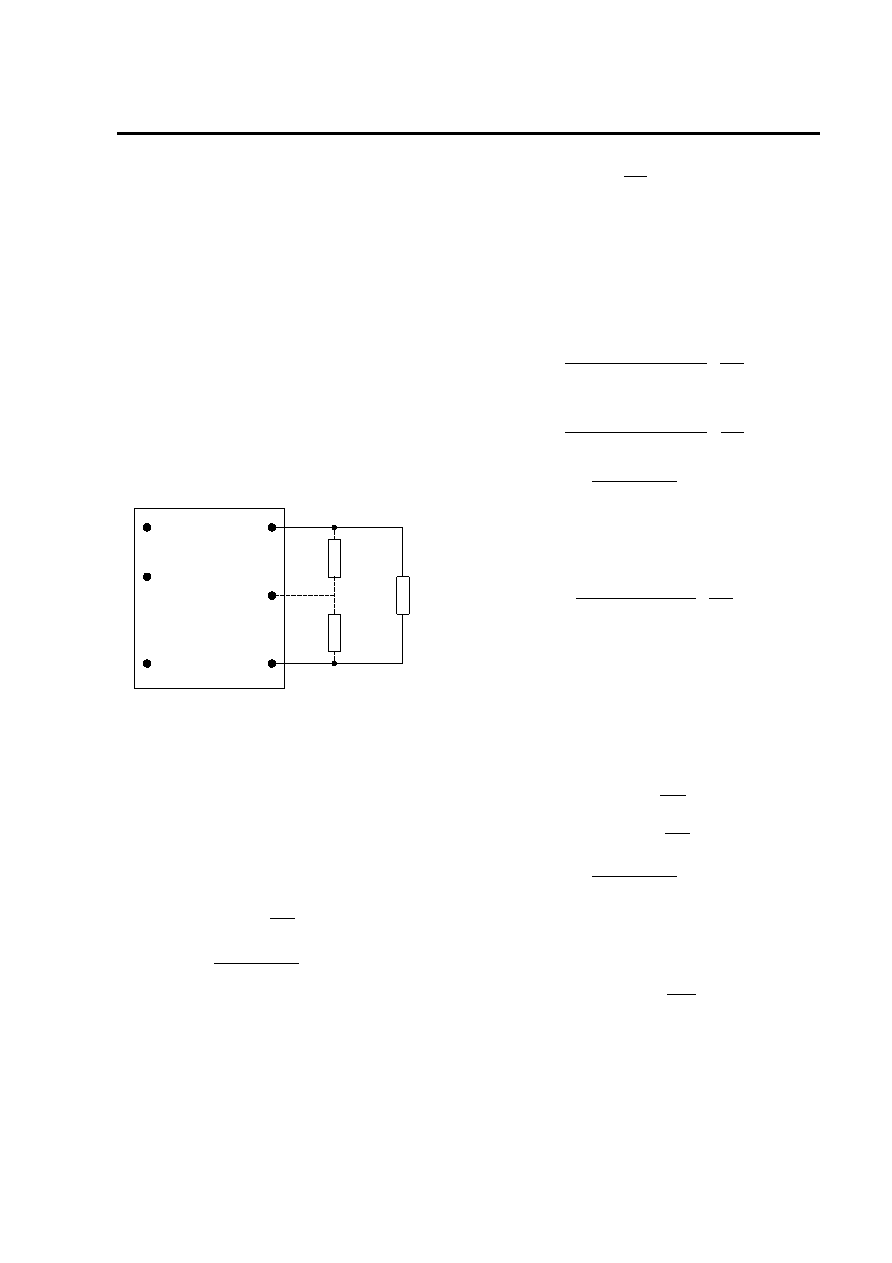
Output Voltage Programming
Trimming allows the output voltage set point to be
increased or decreased, this is accomplished by
connecting an external resistor between the TRIM pin
and either the V
100
%
,
×
=
Δ
set
o
set
o
desired
V
Where
(+) pin or the V (-) pin.
O
For example, to trim-up the output voltage of 1.2V
module (KW025A0P/P1) by 5% to 1.26V, R
VO(+)
VOTRIM
VO(-)
Rtrim-down
LOAD
VIN(+)
ON/OFF
VIN(-)
Rtrim-up
trim-up is
calculated is as follows:
5
%
=
Δ
ΚΩ
×
+
×
=
22
.
10
5
511
5
6
.
0
)
5
100
(
2
.
1
11
.
5
up
trim
R
ΚΩ
=
2
.
102
up
trim
R
Alternative voltage programming for output
voltage: 1.2V (-V Option)
An alternative set of trimming equations is available
as an option for 1.2V output modules, by ordering the
–V option. These equations will reduce the resistance
of the external programming resistor, making the
impedance into the module trim pin lower for
applications in high electrical noise applications.
Figure 42. Circuit Configuration to Trim Output
Voltage.
Connecting an external resistor (Rtrim-down) between
the TRIM pin and the Vo(-) (or Sense(-)) pin
decreases the output voltage set point. To maintain
set point accuracy, the trim resistor tolerance should
be ±1.0%.
ΚΩ
Δ
=
2
%
100
down
trim
R
ΚΩ
Δ
=
%
100
up
trim
R
The following equation determines the required
external resistor value to obtain a percentage output
voltage change of Δ%
100
%
,
×
=
Δ
set
o
set
o
desired
V
Where
For output voltage: 1.2V to 12V
ΚΩ
Δ
=
22
.
10
%
511
down
trim
R
For example, to trim-up the output voltage of 1.2V
module (KW025A0P/P1-V) by 5% to 1.26V, Rtrim-up is
calculated is as follows:
100
%
,
×
=
Δ
set
o
desired
set
o
V
Where
5
%
=
Δ
ΚΩ
=
5
100
up
trim
R
For example, to trim-down the output voltage of 2.5V
module (KW020A0G/G1) by 8% to 2.3V, Rtrim-down
is calculated as follows:
ΚΩ
=
0
.
20
up
trim
R
The value of the external trim resistor for the optional
–V 1.2V module is only 20% of the value required with
the standard trim equations.
8
%
=
Δ
相关PDF资料 |
PDF描述 |
|---|---|
| KAP12AFF | SILICON, RECTIFIER DIODE |
| KAP12DFF | SILICON, RECTIFIER DIODE |
| KAP12FCF | 3 PHASE, SILICON, RECTIFIER DIODE |
| KAP24ALF | SILICON, RECTIFIER DIODE |
| KAP24CCF | SILICON, RECTIFIER DIODE |
相关代理商/技术参数 |
参数描述 |
|---|---|
| KW025A0Y41-SRZ | 功能描述:DC/DC转换器 48Vin 1.8Vout 25A SMT RoHS:否 制造商:Murata 产品: 输出功率: 输入电压范围:3.6 V to 5.5 V 输入电压(标称): 输出端数量:1 输出电压(通道 1):3.3 V 输出电流(通道 1):600 mA 输出电压(通道 2): 输出电流(通道 2): 安装风格:SMD/SMT 封装 / 箱体尺寸: |
| KW025A0Y41Z | 功能描述:DC/DC转换器 48Vin 1.8Vout 25A TH RoHS:否 制造商:Murata 产品: 输出功率: 输入电压范围:3.6 V to 5.5 V 输入电压(标称): 输出端数量:1 输出电压(通道 1):3.3 V 输出电流(通道 1):600 mA 输出电压(通道 2): 输出电流(通道 2): 安装风格:SMD/SMT 封装 / 箱体尺寸: |
| KW025A0Y641Z | 制造商:LINEAGEPOWER 制造商全称:LINEAGEPOWER 功能描述:36 - 75Vdc Input; 1.2 to 5.0Vdc Output; 10 to 25A Output current |
| KW103G2 | 功能描述:THERMISTOR NTC 10K OHM +/-0.50 C RoHS:否 类别:传感器,转换器 >> 热敏电阻 - NTC 系列:KW 标准包装:100 系列:* |
| KW103J2 | 功能描述:NTC THERMISTOR 10K OHM 0.5C BEAD 制造商:us sensor/littelfuse inc 系列:KW 包装:散装 零件状态:在售 25°C 时欧姆阻值:10k 电阻容差:±0.5°C B 值容差:- B0/50:3892K B25/50:- B25/75:- B25/85:- B25/100:- 工作温度:120°C 功率 - 最大值:30mW 长度 - 引线:1.50"(38.00mm) 安装类型:自由悬挂 封装/外壳:圆珠,环氧树脂 标准包装:1 |
发布紧急采购,3分钟左右您将得到回复。