- 您现在的位置:买卖IC网 > PDF目录39185 > L6232E (STMICROELECTRONICS) BRUSHLESS DC MOTOR CONTROLLER, 3.5 A, PQCC28 PDF资料下载
参数资料
| 型号: | L6232E |
| 厂商: | STMICROELECTRONICS |
| 元件分类: | 运动控制电子 |
| 英文描述: | BRUSHLESS DC MOTOR CONTROLLER, 3.5 A, PQCC28 |
| 封装: | PLASTIC, LCC-28 |
| 文件页数: | 4/10页 |
| 文件大小: | 114K |
| 代理商: | L6232E |
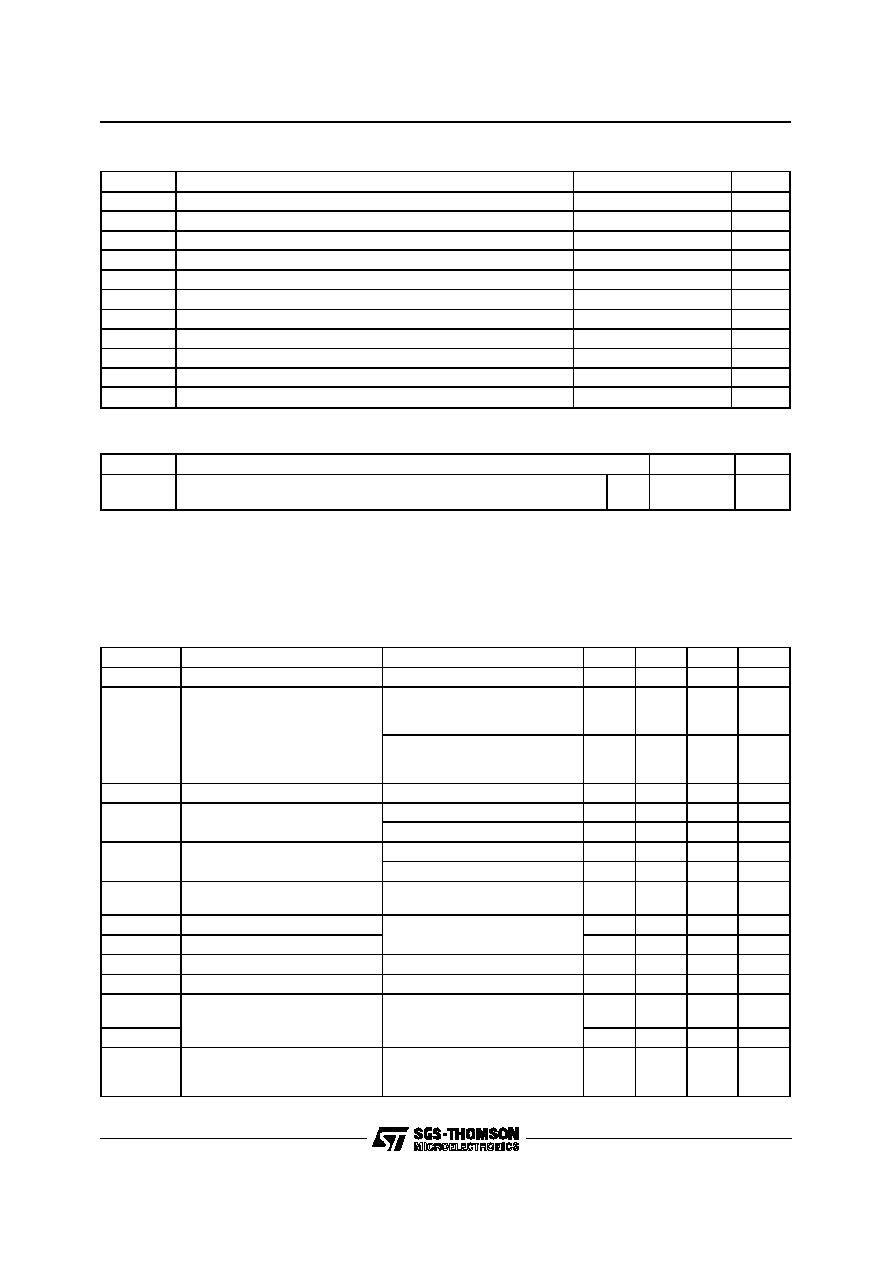
THERMAL DATA
Symbol
Description
Value
Unit
Rth j-pin
Rth j-amb
Thermal Resistance Junction-pins
Thermal Resistance Junction-ambient (**)
Max.
14
52
°C/W
Notes
(*) Pulse width (limited only by junction temperature and by the transient thermal resistance.
(**) Mounted on board with 16cm
2 35
m thickness copper area on board heatsink.
ABSOLUTE MAXIMUM RATINGS
Symbol
Parameter
Value
Unit
VDS sus
Peak Output Sustaining Voltage
15
V
VS
Supply Voltage
15
V
VOpeak
Output Peak Voltage (tpK =5
sec; 10% d.c.)
18
V
VCp
Charge Pump Input Voltage
30
V
Vi
Logic Input Voltage
-0.3 to 7
V
VREF
PWM VREF--LIN VREF Input Voltage
-0.3 to 7
V
Vis
Sense Input Voltage
-1 to 7
V
Ip
Sink-Source Peak Output Current (*)
3.5
A
IO
Sink-Source DC Output Current
1.8
A
Ptot
Total Power Dissipation (Tamb =70
°C)
1.5
W
Tstg,Tj
Storage and Junction Temperature
-40 to 150
°C
ELECTRICAL CHARACTERISTICS (See the block diagram, VS =12V, R = 100K
; C = 180pF;
Tj =25
°C, unless otherwise specified)
Symbol
Parameter
Test Condition
Min.
Typ.
Max.
Unit
VS
Supply Voltage
10.5
12
13.5
V
IS
Quiescent Supply Current
BRK = L; INUA = INUB = INUC
= L; INLA = INLB = INLC = H;
Table 1
0.3
0.5
mA
BRK = H; INUA = INUB = INUC
= H; INLA = INLB = INLC = L;
Table 1
46
mA
IOL
Output Leakage Current
VO =VS = 13.5V
1
mA
RDSon
Sink Out ON Resistance
Tj =25
°C (see Fig.4)
0.42
0.47
Tj = 125
°C
0.7
RDSon
Source Out ON Resistance
Tj =25
°C (see Fig.4)
0.42
0.47
Tj = 125
°C
0.7
VF
Body Diode Forward Drop (sink
and source)
IDS = 1A (see Fig. 6)
1
1.5
V
td(BRK)
Brake Delay Time
See Fig. 1, 3; note1
210
ms
TBRK
Braking Time
10
s
IB(LIN)
LIN Vref Input Bias Current
LIN Vref = 0.4 to 5.5V
400
950
nA
IB(PWM)
PWM Vref Input Bias Current
PWM Vref = 0.4 to 5.5V
400
950
nA
LIN Vref
Reference Voltage Input
Note 2; RS = 0.5
Imotor (PWM) = 1A
Imotor (LIN) = 200mA
2V
PWM Vref
0.4
V
Gv
Sense Amplifier Voltage Gain
PWM Vref = 2.5V,
LIN Vref = 0.4V,
RS = 0.5
; Note 2
3.7
4
4.3
V/V
L6232E
3/10
相关PDF资料 |
PDF描述 |
|---|---|
| L6234 | BRUSHLESS DC MOTOR CONTROLLER, 5 A, PDIP20 |
| L6234PD | BRUSHLESS DC MOTOR CONTROLLER, 5 A, PDSO20 |
| L6235PD | BRUSHLESS DC MOTOR CONTROLLER, 5.6 A, PDSO36 |
| L6235N | BRUSHLESS DC MOTOR CONTROLLER, 5.6 A, PDIP24 |
| L6235D | BRUSHLESS DC MOTOR CONTROLLER, 5.6 A, PDSO24 |
相关代理商/技术参数 |
参数描述 |
|---|---|
| L6233 | 制造商:未知厂家 制造商全称:未知厂家 功能描述:Analog IC |
| L6233P | 制造商:未知厂家 制造商全称:未知厂家 功能描述:Analog IC |
| L6234 | 功能描述:马达/运动/点火控制器和驱动器 Three Phase Motor RoHS:否 制造商:STMicroelectronics 产品:Stepper Motor Controllers / Drivers 类型:2 Phase Stepper Motor Driver 工作电源电压:8 V to 45 V 电源电流:0.5 mA 工作温度:- 25 C to + 125 C 安装风格:SMD/SMT 封装 / 箱体:HTSSOP-28 封装:Tube |
| L6234 | 制造商:STMicroelectronics 功能描述:IC HALF BRIDGE DRIVER TRIPLE 6234 |
| L6234D | 制造商:STMicroelectronics 功能描述: |
发布紧急采购,3分钟左右您将得到回复。