- 您现在的位置:买卖IC网 > PDF目录39185 > L6232E (STMICROELECTRONICS) BRUSHLESS DC MOTOR CONTROLLER, 3.5 A, PQCC28 PDF资料下载
参数资料
| 型号: | L6232E |
| 厂商: | STMICROELECTRONICS |
| 元件分类: | 运动控制电子 |
| 英文描述: | BRUSHLESS DC MOTOR CONTROLLER, 3.5 A, PQCC28 |
| 封装: | PLASTIC, LCC-28 |
| 文件页数: | 7/10页 |
| 文件大小: | 114K |
| 代理商: | L6232E |
mize noise effects(EMI). LIN Vref and PWM Vref
are connected to a comparator whose output is
fed to the logic . The upper and lower DMOS
driver slew-rates are controlled by the internal
logic.
In PWM mode, the upper driver is turned-off when
the motor current reaches the intended value. An
internal One-Shot pulse determines the lenght of
time the upper driver stays off before turning on
again. The pulse width, and thus the cutoff time
(toff), is configurable by means of the external RC
network connected to the RC pin. (see Fig. 2). The
resistor at the RC pin, therefore determines both
the driver output slew-rate during linear mode and
the off-time constant during PWM. The lower driver
is always on during PWM mode of operation; an
on-chip 2
s mask can prevent the beginning of a
new cutoff time because of transient current spikes
caused by the upper drivers turn-on.
The driving mode is determined by the smaller of
the two controlling input voltages. In a typical ap-
plication the motor start-up would occur in PWM
mode to limit power dissipation, with on-speed
control then performed in linear mode.
Thermal protection circuitry will shut-off all drivers
when the chip junction temperature exceeds the
threshold temperature. A small amount of hyster-
esis is included to prevent rapid on/off cycling of
the power stages.
Additional protection is provided against driver input
combinations where the upper and lower drivers of
a half bridge are turned on simultaneusly, resulting
in a short from supply to ground. The chip logic will
cause both the upper and lower drivers involved to
turn-off. (see Table 1)
APPLICATION INFORMATION
A typical application configuration of the L6232E
driving a three-phase brushless DC motor is
shown in Fig.3. The spindle motor is a 4 ohm-
2mH per phase, star connected. This load re-
quires a suitable compensation of the linear con-
trol loop that can be achieved by Rc= 10 Kohm
and Cc= 10nF (R3;C8). Changing the motor char-
acteristics, the RcCc network would be modified
for the best performances of the system. At the
start-up the spindle is driven in PWM mode fixed
toff time.
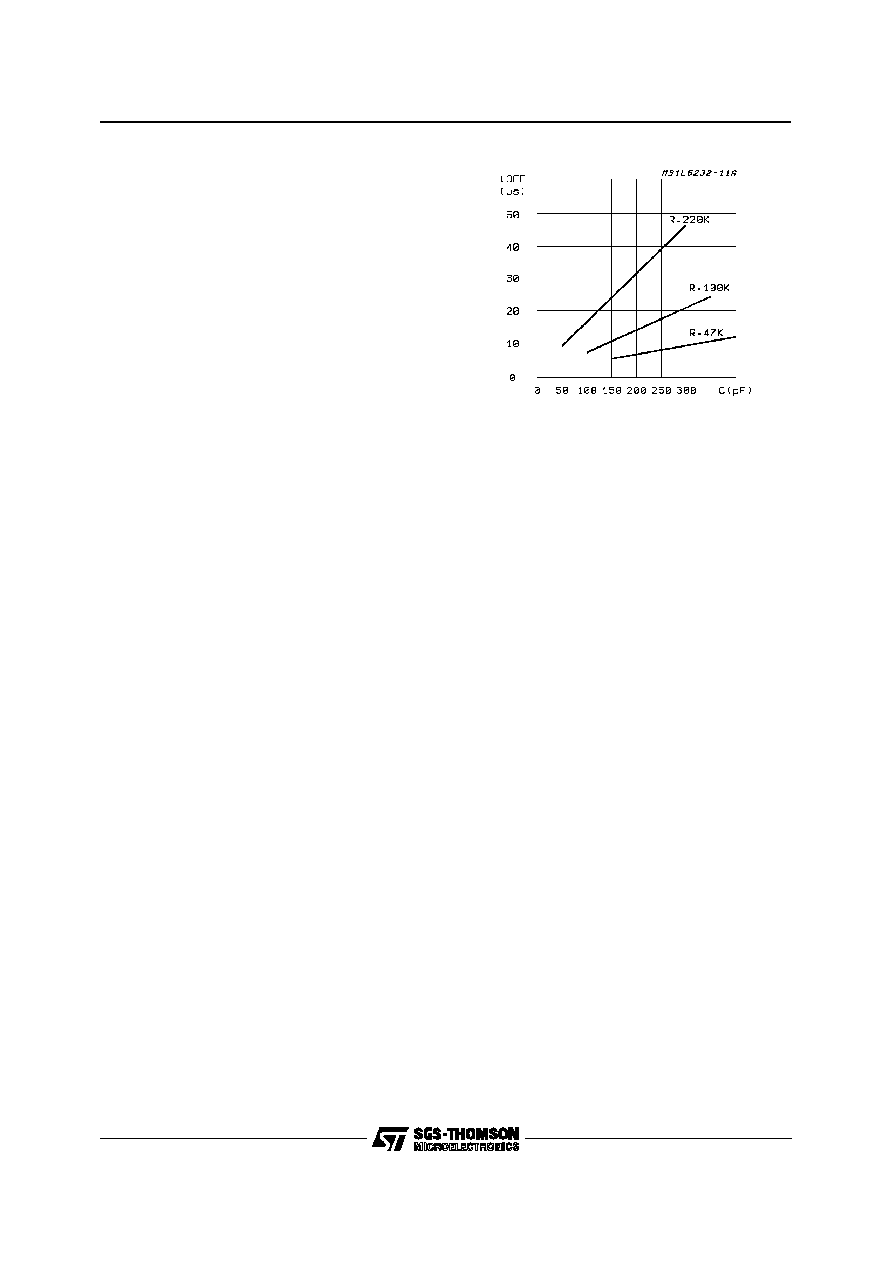
The off-time is calculated by the formula :
toff = 0.69 R2 C7
See fig.2 for a quick choice of the needed capaci-
tor, after the resistor has been fixed. The value of
the resistor defines the rate at which the upper
and lower drivers turn-off during linear mode op-
eration to avoid EMI effects. During turn-off, the
slew rate is constant for the sink stage, while it
has a varying slope for the source stage because
of the non linear change of the gate to source im-
pedance of the DMOS transistor. Practically, the
slowest slew rate is obtained at the sink transistor
switch-off time (see fig. 5), then it increases dur-
ing the first period of the source transistor switch-
off (source,1st) and it becomes the fastest during
the final portion of the turn-off duration (source,
2nd). The PWM to linear mode of operation is
switched by decreasing the LIN Vref level under
the PWM Vref value that could be fixed and cal-
culated by:
PWM Vref = 4 Rs Ip
where Ip is the peak chopping current in the mo-
tor windings. Of course, when the required RPM
is reached, it become of no need a strong torque
and the LIN Vref starting from a value higher than
the calculated PWM Vref, decreases to the value
:
LIN Vref = 4 Rs Im
where Im, smaller than Ip, is the needed motor cur-
rent to keep constant spin. This last reference volt-
age is generally a PLL output driven by speed
transducers coupled to the spindle (like Hall effect
sensors or BEMF processors). To drive the upper
DMOS and during the brake function a voltage
higher than the supply Vs is needed. The charge
pump integrated in the L6232E keeps C3 at the
correct voltage. To guarantee efficient braking of
the motor , C3 must be chosen of adeguate quality
(very high equivalent parallel resistance). C4 can
be a ceramic disk capacitor . The typical applica-
tion od the L6232E is in HDD systems on which
there is the need to park the Read-Write Heads be-
fore the motor braking. This behavior is possible
with the circuit of Fig.3. At Power Supply switch-off
(see Fig. 1), VP falls down and drives down the
BRK input (Active Low). D1 insulates the L6232E
from the power suppy output while the power out-
put stage is switched in a high impedance state.
The spindle motor acting as a three-phase alterna-
tor supplies the Heads voice coil motor driven
through integrateddiodes that rectifie the EMF. Af-
ter a delay longer than the parking time, the lower
output DMOS are switched-on and the spindle mo-
tor is braked. The brake delay time is tipically 150
msec and it is defined by :
Figure 2: Typical toff vs. Capacity of C
L6232E
6/10
相关PDF资料 |
PDF描述 |
|---|---|
| L6234 | BRUSHLESS DC MOTOR CONTROLLER, 5 A, PDIP20 |
| L6234PD | BRUSHLESS DC MOTOR CONTROLLER, 5 A, PDSO20 |
| L6235PD | BRUSHLESS DC MOTOR CONTROLLER, 5.6 A, PDSO36 |
| L6235N | BRUSHLESS DC MOTOR CONTROLLER, 5.6 A, PDIP24 |
| L6235D | BRUSHLESS DC MOTOR CONTROLLER, 5.6 A, PDSO24 |
相关代理商/技术参数 |
参数描述 |
|---|---|
| L6233 | 制造商:未知厂家 制造商全称:未知厂家 功能描述:Analog IC |
| L6233P | 制造商:未知厂家 制造商全称:未知厂家 功能描述:Analog IC |
| L6234 | 功能描述:马达/运动/点火控制器和驱动器 Three Phase Motor RoHS:否 制造商:STMicroelectronics 产品:Stepper Motor Controllers / Drivers 类型:2 Phase Stepper Motor Driver 工作电源电压:8 V to 45 V 电源电流:0.5 mA 工作温度:- 25 C to + 125 C 安装风格:SMD/SMT 封装 / 箱体:HTSSOP-28 封装:Tube |
| L6234 | 制造商:STMicroelectronics 功能描述:IC HALF BRIDGE DRIVER TRIPLE 6234 |
| L6234D | 制造商:STMicroelectronics 功能描述: |
发布紧急采购,3分钟左右您将得到回复。