- 您现在的位置:买卖IC网 > PDF目录69003 > L9942 (STMICROELECTRONICS) STEPPER MOTOR CONTROLLER, PDSO36 PDF资料下载
参数资料
| 型号: | L9942 |
| 厂商: | STMICROELECTRONICS |
| 元件分类: | 运动控制电子 |
| 英文描述: | STEPPER MOTOR CONTROLLER, PDSO36 |
| 封装: | POWER, SO-36 |
| 文件页数: | 5/21页 |
| 文件大小: | 161K |
| 代理商: | L9942 |
Multiplexer MUX1 is used for test purposes. In normal operation the 32kHz clock signal is passed to sig-
nal SBCLK. In test mode however (pin TEST=high) the main clock can be supplied to the peripheral
components and the RC oscillator can be stopped by setting bit TEST of oscillator control register
OSCR.
Multiplexer MUX2 is used to select main clock or standby clock for TIMER1 and watchdog under control
of signal STOP which is active in STOP mode of the CPU.
The RC oscillator is designed to minimize frequency offset caused by temperature, supply voltage,
manufacturing tolerances. Nevertheless the deviation from 32kHz might be larger than required and tun-
ing will become necessary. For that purpose the RC oscillator frequency can be measured and adjusted
under control of the CPU as described in the following (see also fig. 7).
The device is in normal operation mode (pin TEST=low). The standby oscillator is controlled by oscillator
control register OSCR. Setting bit TEST of OSCR will connect the TIMER1 input with signal GATE via
MUX3. The timer now has to be initialized and programmed to input gated mode. In this mode it will
count clock pulses (fMAINCLK
±12) as long as its input is high. If bit COUNT of OSCR is set now, the block
COUNT LOGIC generates one pulse at signal GATE with the length of exactly one period of the RC os-
cillator clock signal. Therefore the timer will count main/oscillator pulses for one period of the standby
clock. At the falling edge of signal GATE bit READY of OSCR is set indicating the end of the measure-
ment. Now the timer can be read by the CPU to determine the actual frequency of the standby oscillator.
Bits TEST, COUNT, READY can be cleared now. As long as COUNT is set, READY can not be cleared
by software.
Timer resolution at fMAINCLK = 8MHz is 12
125ns = 1.5s.
Measurement of a clock period of TGATE = 1/32kHz = 31.3
s therefore shows a resolution of about 5%.
The RC oscillator has a nominal frequency of 32kHz and can be adjusted with frequency control bits
FC2, 1, 0. Adjustment is performed in steps of 4kHz (i. e. 12.5%) from 16kHz to 44kHz as shown in the
following table.
FC2
FC1
FC0
fRCOSC/kHz
00
0
44
00
1
40
01
0
36
01
1
32
10
0
28
10
1
24
11
0
20
11
1
16
Register OSCR is cleared at system reset. Therefore the highest frequency of RC oscillator is selected.
Bits 5 and 6 are not implemented. They are read as zero.
MICROCONTROLLER SECTION (continued)
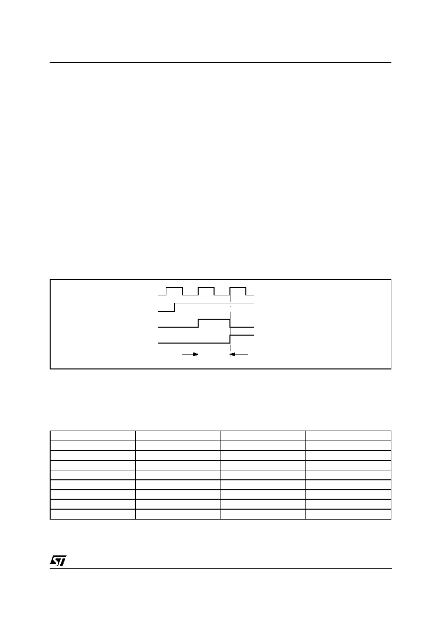
SBCLK
COUNT
GATE
READY
TGATE
=1/fSBCLK
TGATE
Figure 7. Signals of RC oscillator count logic.
L9942
13/21
相关PDF资料 |
PDF描述 |
|---|---|
| LA5681FN | SWITCHING CONTROLLER, 520 kHz SWITCHING FREQ-MAX, QCC48 |
| LB11620T | BRUSHLESS DC MOTOR CONTROLLER, 0.25 A, PDSO24 |
| LB11875 | BRUSHLESS DC MOTOR CONTROLLER, 0.03 A, PDSO36 |
| LB11923V | BRUSHLESS DC MOTOR CONTROLLER, 0.03 A, PDSO44 |
| LB11923V | BRUSHLESS DC MOTOR CONTROLLER, 0.03 A, PDSO44 |
相关代理商/技术参数 |
参数描述 |
|---|---|
| L9942XP1 | 功能描述:低压差稳压器 - LDO Integrated Stepper Bipolar Motor Driver RoHS:否 制造商:Texas Instruments 最大输入电压:36 V 输出电压:1.4 V to 20.5 V 回动电压(最大值):307 mV 输出电流:1 A 负载调节:0.3 % 输出端数量: 输出类型:Fixed 最大工作温度:+ 125 C 安装风格:SMD/SMT 封装 / 箱体:VQFN-20 |
| L9942XP1TR | 功能描述:马达/运动/点火控制器和驱动器 Integrated Stepper Bipolar Motor Driver RoHS:否 制造商:STMicroelectronics 产品:Stepper Motor Controllers / Drivers 类型:2 Phase Stepper Motor Driver 工作电源电压:8 V to 45 V 电源电流:0.5 mA 工作温度:- 25 C to + 125 C 安装风格:SMD/SMT 封装 / 箱体:HTSSOP-28 封装:Tube |
| L9946 | 制造商:未知厂家 制造商全称:未知厂家 功能描述:DC Motor Controller/Driver |
| L9947 | 制造商:STMICROELECTRONICS 制造商全称:STMicroelectronics 功能描述:QUAD HALF-BRIDGE AND SINGLE HIGH-SIDE DRIVER |
| L9947L | 制造商:STMicroelectronics 功能描述: |
发布紧急采购,3分钟左右您将得到回复。