- 您现在的位置:买卖IC网 > PDF目录69003 > L9942 (STMICROELECTRONICS) STEPPER MOTOR CONTROLLER, PDSO36 PDF资料下载
参数资料
| 型号: | L9942 |
| 厂商: | STMICROELECTRONICS |
| 元件分类: | 运动控制电子 |
| 英文描述: | STEPPER MOTOR CONTROLLER, PDSO36 |
| 封装: | POWER, SO-36 |
| 文件页数: | 8/21页 |
| 文件大小: | 161K |
| 代理商: | L9942 |
CAN Controller and Interface
The CAN controller module ST6-CAN1 handles all frame types according to CAN Specification 2.0A.
The module is supplied with a clock signal derived from MAINCLK. The division factor N of the clock pres-
caler (see Fig. 9) defines the baud rate of the module as shown below. N is fixed by mask option to 2.
fMAINCLK = 8.0MHz
N
baud rate / kbit/sec
1
2
3
4
125
62.5
31.25
15.625
With this option a trade off between speed and EMI performance of the bus can be achieved.
The interrupt output of the CAN controller is ored with bus interface interrupt and connected with inter-
rupt input #2. Bit 5 of interrupt option register IOR has to be cleared.
The CAN controller input and output signals are accessible in two ways: via bus line interface or via I/O
ports PA0 and PA1 (see Fig. 8). This is controlled with BUSIE of register BPCR (see section I/O Port).
The input pin BUSIN an the output pin BUSOUT of the CAN line interface can be directly connected to a
single wire VBAT compatible serial bus.
The slew rate SRBUSOUT of the bus output driver is 3 - 6V/
s. It can be adjusted to 0.5 , 1.5 , 2.5 SR
by mask option. The bus input line BUSIN has a supply voltage dependent threshold together with suffi-
cient hysteresis to suppress line spikes. BUSIN and bus output line BUSOUT pins are protected against
overvoltage, short to GND and VS and can also be driven beyond VS and GND. During lack of VS or
GND the output shows high impedance characteristic.
If the voltage at bus input BUSIN exceeds Vin ov an overvoltage condition is recognized and stored in
interrupt flag BOVI of bus interface register BIR. This bit can generate a maskable interrupt request at in-
terrupt input #2. BOVI is RESET by software only. If the overvoltage situation is still present, BOVI re-
mains set. Bits 0 ... 5 of register BIR are not implemented. They are read as zero. This register is
cleared at system reset.
Suppressing all 4 classes of ”Schaffner” signals BUSIN and BUSOUT pins can be loaded with short en-
ergy pulses of max.
±0.2mJ. All these features together with a high possible baud rate of 125kbaud,
controlled output slope for low EMI and a wide operating range make this interface suitable for automo-
tive bus system.
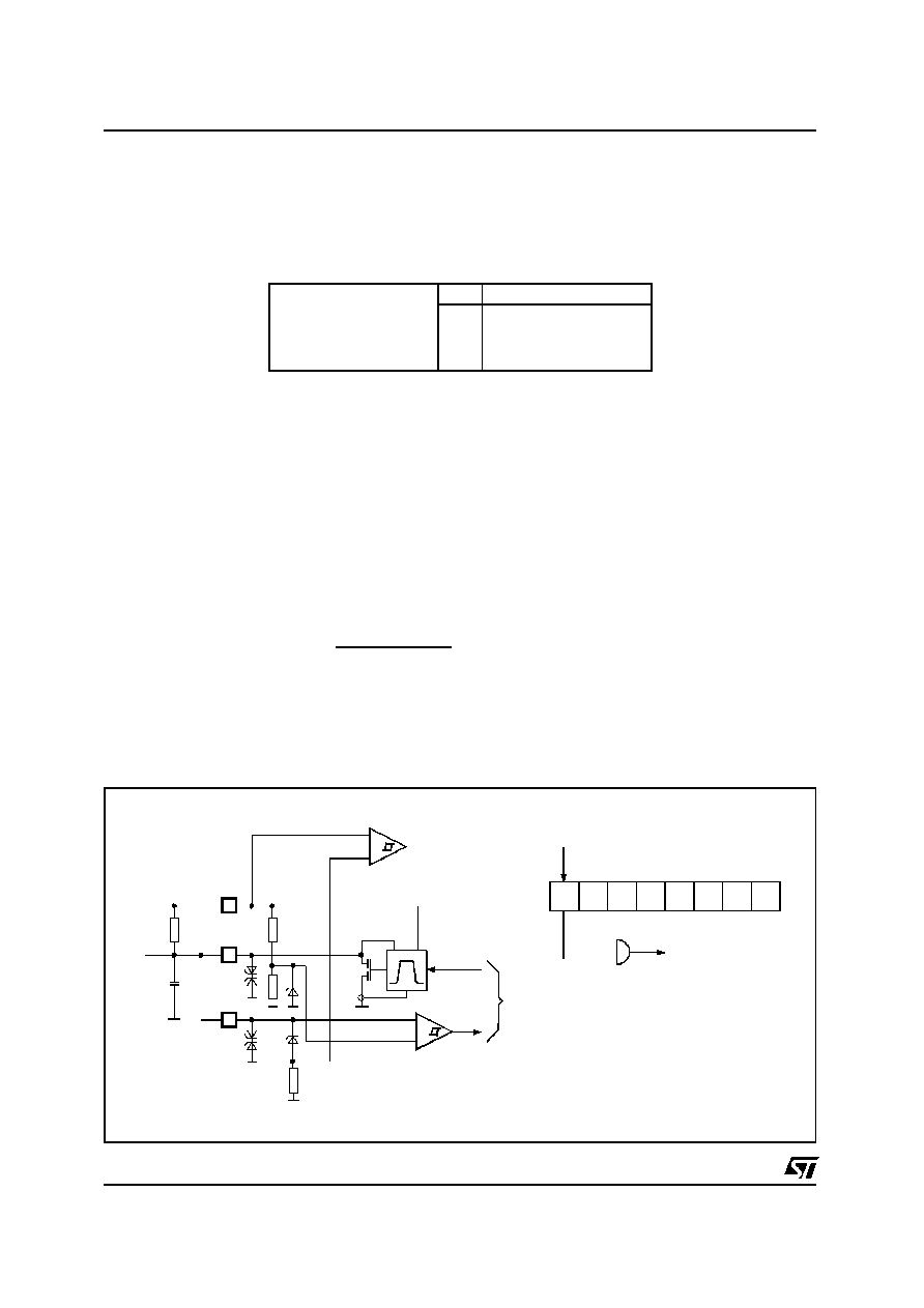
MICROCONTROLLER SECTION (continued)
-
+
OUT
IN
BOVI BIE
BIR
INT#2
-
+
VBAT
RPU
C L
Bus
to CAN Controller
VS
BUSOUT
BUSIN
Figure 9. CAN Bus Line Interface Block Diagram.
L9942
16/21
相关PDF资料 |
PDF描述 |
|---|---|
| LA5681FN | SWITCHING CONTROLLER, 520 kHz SWITCHING FREQ-MAX, QCC48 |
| LB11620T | BRUSHLESS DC MOTOR CONTROLLER, 0.25 A, PDSO24 |
| LB11875 | BRUSHLESS DC MOTOR CONTROLLER, 0.03 A, PDSO36 |
| LB11923V | BRUSHLESS DC MOTOR CONTROLLER, 0.03 A, PDSO44 |
| LB11923V | BRUSHLESS DC MOTOR CONTROLLER, 0.03 A, PDSO44 |
相关代理商/技术参数 |
参数描述 |
|---|---|
| L9942XP1 | 功能描述:低压差稳压器 - LDO Integrated Stepper Bipolar Motor Driver RoHS:否 制造商:Texas Instruments 最大输入电压:36 V 输出电压:1.4 V to 20.5 V 回动电压(最大值):307 mV 输出电流:1 A 负载调节:0.3 % 输出端数量: 输出类型:Fixed 最大工作温度:+ 125 C 安装风格:SMD/SMT 封装 / 箱体:VQFN-20 |
| L9942XP1TR | 功能描述:马达/运动/点火控制器和驱动器 Integrated Stepper Bipolar Motor Driver RoHS:否 制造商:STMicroelectronics 产品:Stepper Motor Controllers / Drivers 类型:2 Phase Stepper Motor Driver 工作电源电压:8 V to 45 V 电源电流:0.5 mA 工作温度:- 25 C to + 125 C 安装风格:SMD/SMT 封装 / 箱体:HTSSOP-28 封装:Tube |
| L9946 | 制造商:未知厂家 制造商全称:未知厂家 功能描述:DC Motor Controller/Driver |
| L9947 | 制造商:STMICROELECTRONICS 制造商全称:STMicroelectronics 功能描述:QUAD HALF-BRIDGE AND SINGLE HIGH-SIDE DRIVER |
| L9947L | 制造商:STMicroelectronics 功能描述: |
发布紧急采购,3分钟左右您将得到回复。