- 您现在的位置:买卖IC网 > PDF目录30714 > LA1265 AM/FM, AUDIO SINGLE CHIP RECEIVER, PDIP22 PDF资料下载
参数资料
| 型号: | LA1265 |
| 元件分类: | 接收器 |
| 英文描述: | AM/FM, AUDIO SINGLE CHIP RECEIVER, PDIP22 |
| 封装: | SDIP-22 |
| 文件页数: | 10/15页 |
| 文件大小: | 705K |
| 代理商: | LA1265 |
LA1265
No. 1820- 4/15
How to use the LA1265
1. LED lighting, muting drive output, stop signal (SD).
For LED lighting, muting drive output, stop signal, the output at pin 8 is used.
The voltage on pin 8, when tuned, turns from "H" to "L". (Active-Low)
Signal bandwidth at pin 8.
For AM, the bandwidth depends on the CF (BFU450CN)
at pin 11. If a capacitor is connected in place of the CF,
the bandwidth will get wider.
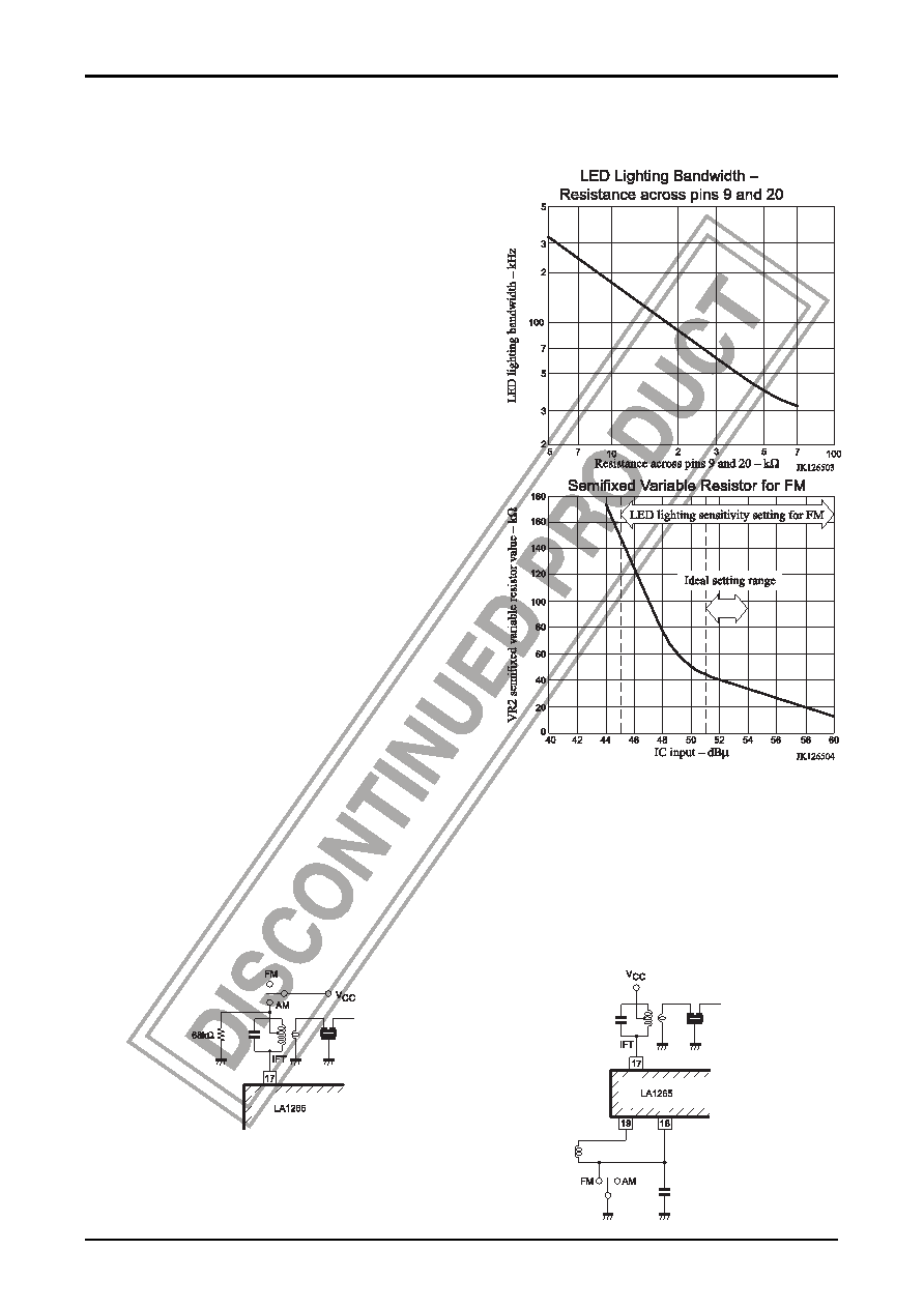
For FM, the bandwidth depends on the resistance across
pins 9 and 20. If the resistance is increased, the
bandwidth will get narrower. R = 15k
Ω makes the
bandwidth approximately 120kHz.
Sensitivity adjustment of LED, muting, stop signal.
For FM, the semifixed variable resistor across pin 13 and
GND is used.
For AM, the semifixed variable resistor across pins 13
and 14 is used. Be sure to start adjustment for FM, and
then make adjustment for AM. For the stop signal
sensitivity and FM stop signal bandwidth, the variations
should be considered and it is recommended to use the
semifixed variable resistor for adjustment.
LED lighting sensitivity setting for AM.
For the LED lighting sensitivity setting for AM, it is
desirable that the IC input be 30dB
μ (antenna input :
approximately 50dB/m). In this case, the value of VR1 is
30k
Ω.
LED lighting sensitivity setting for FM.
For the LED lighting sensitivity setting for FM, the IC
input may be 45dB
μ to 60dBμ. With the variations in the
front end considered, it is ideal that the IC input in a
standard receiving set be 51dB
μ to 54dBμ. The lower
value of VR2 for the LED lighting sensitivity setting is as
illustrated right. Since the variations in the front end
cause the IC input setting sensitivity to vary, it is
recommended to use a value of VR2 at an input voltage
lower than a standard setting by 6dB or greater. For example, if IC input 53dB
μ is taken as a standard, use
VR2
≤ 100kΩ at IC input 47dBμ.
2. AM/ FM changeover
Two selections are available for changeover as shown below : (A) pin 17-used method and (B) pin 18-used method.
For (A), the voltage on pin 17 relative to VCC (pin 7) must be within the range of 0.8V to +0.1V. If not within this
range, distortion and selectivity will get worse.
For (A), a resistance of 68k
Ω at the IFT cold terminal, which is used to prevent the changeover circuit from
malfunctioning, must be connected.
(A) pin 17-use method for AM/FM changeover
(B) Pin 18-used method for AM/FM changeover
相关PDF资料 |
PDF描述 |
|---|---|
| LA1266 | AM/FM, AUDIO SINGLE CHIP RECEIVER, PDIP24 |
| LA1267 | AM/FM, AUDIO SINGLE CHIP RECEIVER, PDIP24 |
| LA1351 | 2 CHANNEL(S), EQUALIZER CIRCUIT, PSIP26 |
| LA1360 | 2 CHANNEL(S), EQUALIZER CIRCUIT, PSIP26 |
| LA1357N | 1 CHANNEL, VIDEO AMPLIFIER, PDIP22 |
相关代理商/技术参数 |
参数描述 |
|---|---|
| LA1266 | 制造商:SANYO 制造商全称:Sanyo Semicon Device 功能描述:AM/FM Tuner System Of Electronic Tuning Type |
| LA1267 | 制造商:SANYO 制造商全称:Sanyo Semicon Device 功能描述:FM/AM Tuner of Electronic Tuning Type |
| LA126B-3-SR | 制造商:LIGITEK 制造商全称:LIGITEK electronics co., ltd. 功能描述:LED ARRAY |
| LA1270 | 制造商:未知厂家 制造商全称:未知厂家 功能描述: |
| LA1270M | 制造商:未知厂家 制造商全称:未知厂家 功能描述:Analog IC |
发布紧急采购,3分钟左右您将得到回复。