- 您现在的位置:买卖IC网 > PDF目录30714 > LA1265 AM/FM, AUDIO SINGLE CHIP RECEIVER, PDIP22 PDF资料下载
参数资料
| 型号: | LA1265 |
| 元件分类: | 接收器 |
| 英文描述: | AM/FM, AUDIO SINGLE CHIP RECEIVER, PDIP22 |
| 封装: | SDIP-22 |
| 文件页数: | 11/15页 |
| 文件大小: | 705K |
| 代理商: | LA1265 |
LA1265
No. 1820- 5/15
3. Local OSC buffer output
When local OSC buffer output wave form is saw-toothed at the SW mode, connect a resistance of 1.2k
Ω or
thereabouts across pin 22 and GND.
4. AM input pin
It is desirable that the AM input pin (pin 19) be L-coupled to pin 18.
Inputting to pin 19 can be done by DC-cutting with a capacitor. However, an unbalance in the RF amplifier
(differential amplifier) causes gain drop and whistle worsening.
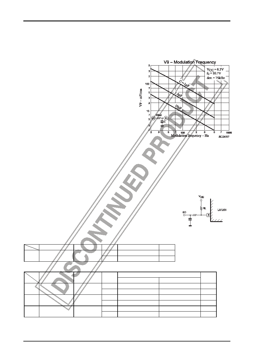
5. Capacitance across pin 9 and GND.
A large capacitance across pin 9 and GND may cause a
misstop at an adjacent channel when the channel select
speed is made faster at the automatic channel select mode. In
this case, decrease the capacitance across pin 9 and GND.
However, if too decreased, the LED will flutter at low
modulation frequencies at the time of detuning. Therefore, it
is recommended to fix the capacitance across pin 9 and GND
to be 3.3
μF to 10μF. The relation between modulation
frequency and demodulation output voltage on pin 9 with the
capacitance across pin 9 and GND as a parameter is shown
right.
6. If the coupling coefficient of the local OSC coil is small and an antiresonance point of approximately 100MHz is
present or the stray capacitance across pins 22 and 21 is large, a parasitic oscillation of approximately 100MHz may
occur in the buffer output (pin 22). In this case, connect a capacitance of approximately 30pF across pin 22 and
GND.
7. AM OSC coil
Generally speaking, the following should be noted. Avoid winding with loose coupling between primary side and
secondary side (especially SW1, SW2).
To put it concretely, the pot core type is better than the screw core type which is loose in coupling. This prevents the
local OSC frequency from turning third resonance frequency related to the coupling coefficient.
8. Resistance across pin 8 and VDD.
If pin 8 is used for the stop signal (SD) only, without using LED, it is recommended to
fix resistance RL across pin 8 and GND to be 51kΩ to 100kΩ.
9. To prevent whistle from worsening, make the pattern of AM output pin 12 as short as
possible.
Input/Output Admittance
FM
Parameter
Frequency
Admittance
Unit
ri
330
Ω
IF
γi1
10.7MHz
ci
20
pF
AM
Admittance
Parameter
Frequency
AGC-off (V16 = 1.4V)
AGC-on (V16 = 2.5V)
Unit
ri
15
16
k
Ω
RF
γi19
1MHz
ci
4
pF
ro
k
Ω
MIX
γo17
500kHz
co
3
pF
ri
2
k
Ω
IF
γi15
500kHz
co
10
8
pF
相关PDF资料 |
PDF描述 |
|---|---|
| LA1266 | AM/FM, AUDIO SINGLE CHIP RECEIVER, PDIP24 |
| LA1267 | AM/FM, AUDIO SINGLE CHIP RECEIVER, PDIP24 |
| LA1351 | 2 CHANNEL(S), EQUALIZER CIRCUIT, PSIP26 |
| LA1360 | 2 CHANNEL(S), EQUALIZER CIRCUIT, PSIP26 |
| LA1357N | 1 CHANNEL, VIDEO AMPLIFIER, PDIP22 |
相关代理商/技术参数 |
参数描述 |
|---|---|
| LA1266 | 制造商:SANYO 制造商全称:Sanyo Semicon Device 功能描述:AM/FM Tuner System Of Electronic Tuning Type |
| LA1267 | 制造商:SANYO 制造商全称:Sanyo Semicon Device 功能描述:FM/AM Tuner of Electronic Tuning Type |
| LA126B-3-SR | 制造商:LIGITEK 制造商全称:LIGITEK electronics co., ltd. 功能描述:LED ARRAY |
| LA1270 | 制造商:未知厂家 制造商全称:未知厂家 功能描述: |
| LA1270M | 制造商:未知厂家 制造商全称:未知厂家 功能描述:Analog IC |
发布紧急采购,3分钟左右您将得到回复。