- 您现在的位置:买卖IC网 > PDF目录30725 > LA76810HA AM/FM, AUDIO/VIDEO DEMODULATOR, PDIP54 PDF资料下载
参数资料
| 型号: | LA76810HA |
| 元件分类: | 接收器 |
| 英文描述: | AM/FM, AUDIO/VIDEO DEMODULATOR, PDIP54 |
| 封装: | 0.600 INCH, DIP-54 |
| 文件页数: | 14/41页 |
| 文件大小: | 417K |
| 代理商: | LA76810HA |
第1页第2页第3页第4页第5页第6页第7页第8页第9页第10页第11页第12页第13页当前第14页第15页第16页第17页第18页第19页第20页第21页第22页第23页第24页第25页第26页第27页第28页第29页第30页第31页第32页第33页第34页第35页第36页第37页第38页第39页第40页第41页
LA76810HA
No.A1143-21/41
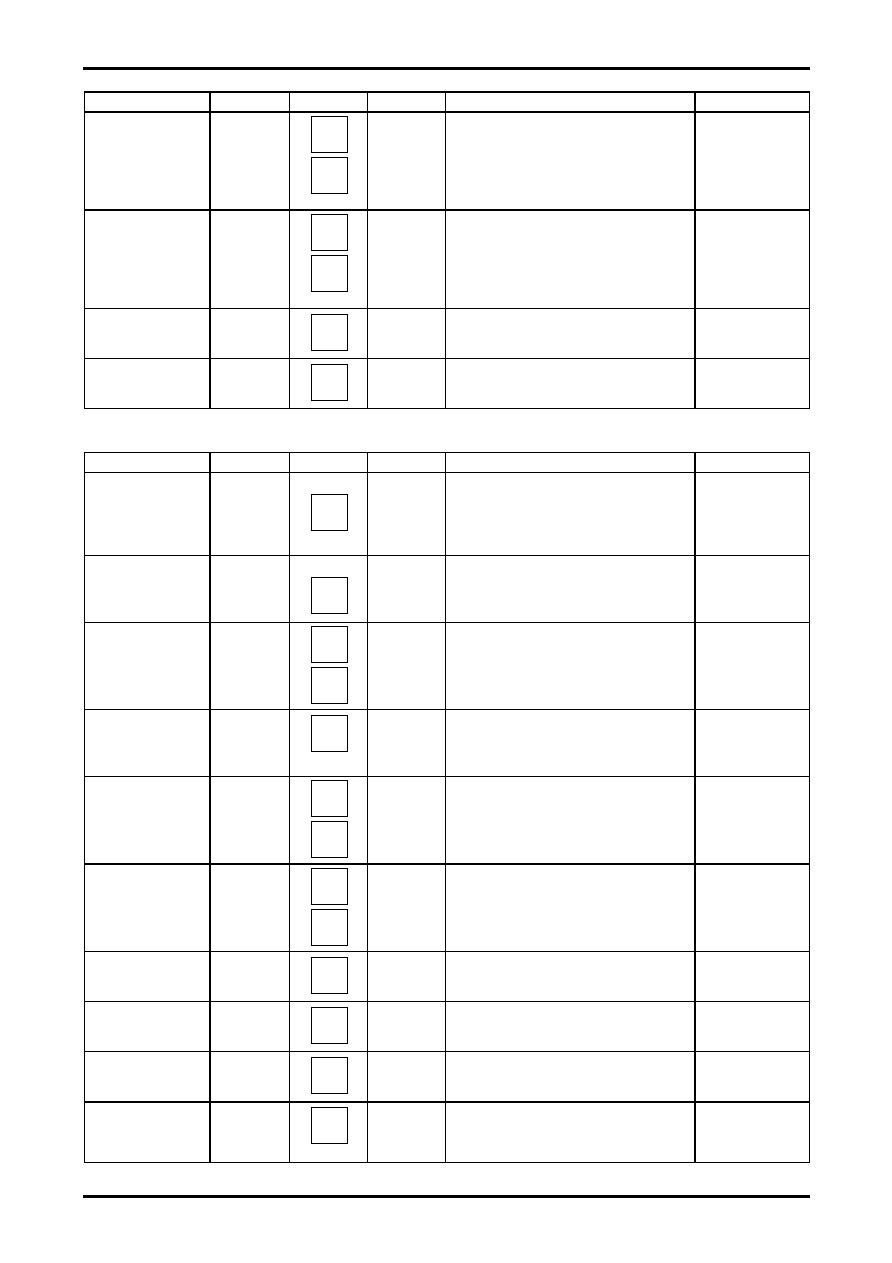
Continued from preceding page.
Input signal
Symbol
Test point
Input signal
Test method
Bus bit/input signal
Demodulation
output ratio
G-Y/R-Y: PAL
GR_P
20
19
C-5
Measure Rout output amplitude Vrp and GOUT
output amplitude Vgbp. And calculate GR_P =
Vgrp/Vrp.
Color: 1000000
Demodulation
angle B-Y/R-Y:
PAL
ANGBR_P
21
19
C-1
Refer to 5. and measure the B-Y and R-Y
demodulation angle and calculate.
Color: 1000000
APC pull-in range (+)
PULIN+_P
21
C-1
Decrease the chroma fsc frequency from
4.433619MHz+1000Hz and measure the
frequency at which the VCO locks.
APC pull-in range (-)
PULIN-_P
21
C-1
Increase the chroma fsc frequency from
4.433619MHz-1000Hz and measure the
frequency at which the VCO locks.
[Chroma block]: NTSC
Input signal
Symbol
Test point
Input signal
Test method
Bus bit/input signal
ACC amplitude
characteristics 1
ACCM1_N
Bout
21
C-1
0dB
+6dB
Measure the output amplitude when 0dB is
applied to the chroma input and the output
amplitude when +6dB is applied to the chroma
input and calculate the ratio between them.
ACCM1 = 20LOG (+6dBdata/0dBdata)
ACC amplitude
characteristics 2
ACCM2_N
Bout
21
C-1
-20dB
Measure the output amplitude when 20dB is
applied to the chroma input and calculate the
ratio between them.
ACCM2 = 20LOG (-20dBdata/0dBdata)
R-Y/B-Y: NTSC
Demodulation
output ratio
R-Y/B-Y: NTSC
RB_N
21
19
C-1
Refer to 5. and measure Bout output amplitude
Vb and ROUT output amplitude Vr. And calculate
RB = Vr/Vb.
Color: 1000000
G-Y/B-Y: NTSC
Demodulation
output ratio
R-Y/B-Y: NTSC
GB_N
20
C-1
Refer to 5. and measure GOUT output amplitude
Vg. And calculate GB_N = Vg/Vb.
Color: 1000000
Demodulation
angle B-Y/R-Y:
NTSC
ANGBR_N
21
19
C-1
Refer to 5. and measure the B-Y and R-Y
demodulation angle and calculate.
Reference: B-Y angle
Color: 1000000
Demodulation
angle G-Y/B-Y:
NTSC
ANGGB_N
21
20
C-1
Refer to 5. and measure the B-Y and G-Y
demodulation angle and calculate.
Reference: B-Y angle
Color: 1000000
Killer operating
point
KILL_N
21
C-1
Reduce the input signal until the output level
becomes 150mVp-p or less. Measure
the input level at that moment.
APC pull-in range (+)
PULIN+_N
21
C-1
Decrease the chroma fsc frequency from
3.579545MHz+1000Hz and measure the
frequency at which the VCO locks.
APC pull-in range (-)
PULIN-_N
21
C-1
Increase the chroma fsc frequency from
3.579545MHz-1000Hz and measure the
frequency at which the VCO locks.
Tint center
TINCEN
21
C-1
Measure each part of the output level and
calculate the B-Y axis angle.
TINT: 1000000
Continued on next page.
相关PDF资料 |
PDF描述 |
|---|---|
| LA76814 | HORIZ/VERT DEFLECTION IC, PDIP54 |
| LA76818A | AM/FM, AUDIO/VIDEO DEMODULATOR, PDIP54 |
| LA76818A | AM/FM, AUDIO/VIDEO DEMODULATOR, PDIP54 |
| LA76835NM | AM/FM, AUDIO/VIDEO DEMODULATOR, PQFP80 |
| LA76835NM | AM/FM, AUDIO/VIDEO DEMODULATOR, PQFP80 |
相关代理商/技术参数 |
参数描述 |
|---|---|
| LA76818A | 制造商:SANYO 制造商全称:Sanyo Semicon Device 功能描述:The LA76818A is I2C bus controller ICs that support the different TV broadcast formats used worldwide and aim for rationalization of color TV set desi |
| LA76820 | 制造商:未知厂家 制造商全称:未知厂家 功能描述:单片多制式TV处理集成电路 |
| LA76828N | 制造商:SANYO 制造商全称:Sanyo Semicon Device 功能描述:电视小信号处理芯片 |
| LA76828N-A-E | 制造商:Sony Semiconductor Solutions Division 功能描述: |
| LA76832N | 制造商:SANYO 制造商全称:Sanyo Semicon Device 功能描述:Monolithic Linear IC I2C Bus Control IC |
发布紧急采购,3分钟左右您将得到回复。