- 您现在的位置:买卖IC网 > PDF目录30725 > LA76810HA AM/FM, AUDIO/VIDEO DEMODULATOR, PDIP54 PDF资料下载
参数资料
| 型号: | LA76810HA |
| 元件分类: | 接收器 |
| 英文描述: | AM/FM, AUDIO/VIDEO DEMODULATOR, PDIP54 |
| 封装: | 0.600 INCH, DIP-54 |
| 文件页数: | 7/41页 |
| 文件大小: | 417K |
| 代理商: | LA76810HA |
第1页第2页第3页第4页第5页第6页当前第7页第8页第9页第10页第11页第12页第13页第14页第15页第16页第17页第18页第19页第20页第21页第22页第23页第24页第25页第26页第27页第28页第29页第30页第31页第32页第33页第34页第35页第36页第37页第38页第39页第40页第41页
LA76810HA
No.A1143-15/41
Continued from preceding page.
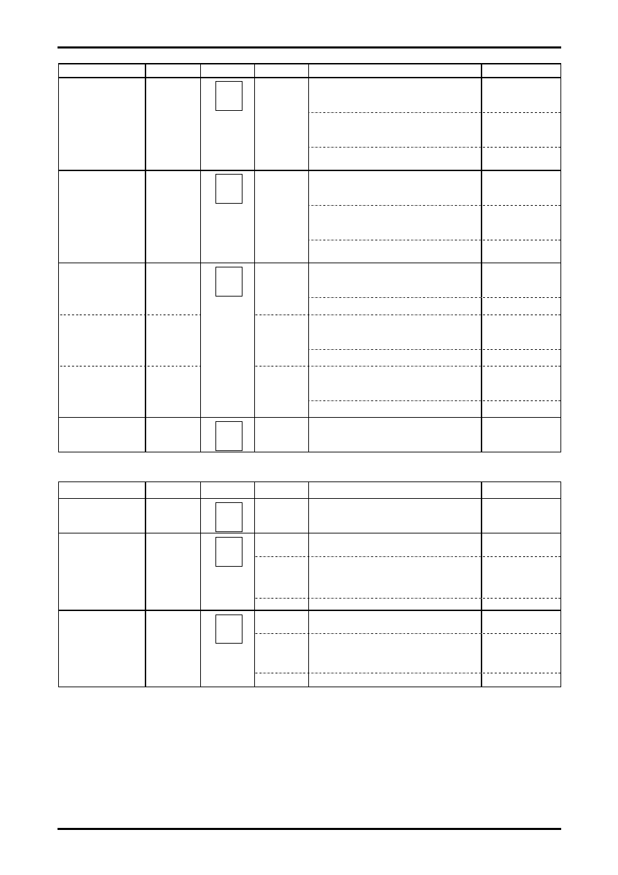
Input signal
Symbol
Test point
Input signal
Test method
Bus bit/input signal
Measure the 0IRE DC level (BKST1 V) at point A
of the output signal in the Black Stretch Defeat
(Black Stretch OFF) mode.
Measure the 0IRE DC level (BKST2 V) at point A
of the output signal in the Black Stretch ON
mode.
Blk Str DEF: 0
Maximum black
stretch gain
BKSTmax
L-BK
Calculate BKSTmax=2
×50× (BKST1-BKST2)
/CNTHB.
Measure the 60IRE DC level (BKST3 V) of the
output signal in the Black Stretch Defeat ON
mode.
Blk Str DEF: 0
Measure the 60IRE DC level (BKST4 V) of the
output signal in the Black Stretch Defeat (Black
Stretch OFF) mode.
Black stretch
threshold
black
(60IRE
black)
BKSTTH
L-60
Calculate BKSTTH
= 50×
(BKST4-BKST3)/CNTHB.
Sharpness
variability
characteristics
With the input signal’s continuous
wave = 2.2MHz, measure the output signal’s
continuous wave amplitude (F00S31 Vp-p).
FILTER SYS:0000
Sharpness: 100000
(normal)
Sharp31
L-CW
Calculate Sharp31 = 20Log (F00S31/PEAKDC).
With the input signal’s continuous
wave = 2.2MHz, measure the output signal’s
continuous wave amplitude (F00S63 Vp-p).
FILTER SYS:0000
Sharpness: 111111
(max)
Sharp63
L-CW
Calculate Sharp63=20Log (F00S63/PEAKDC).
With the input signal’s continuous
wave=2.2MHz, measure the output signal’s
continuous wave amplitude (F00S0 Vp-p).
FILTER SYS:0000
Sharpness: 000000
(min)
Sharp0
L-CW
Calculate Sharp0 = 20Log (F00S0/PEAKDC).
Horizontal/vertical
blanking output
level
RGBBLK
L-100
Measure the DC level (RGBBLK V) for the output
signal’s blanking period.
[OSD block] Bus control bit conditions: Contrast = 63, Brightness = 63
Input signal
Symbol
Test point
Input signal
Test method
Bus bit/input signal
OSD
Fast SW threshold
FSTH
L-0
O-2
Apply voltage to pin 17 and measure the voltage
at pin 17 at the point where the output signal
switches to the OSD signal.
Pin 16A: O-2
applied
L-50
Measure the output signal’s 50IRE amplitude
(CNTCR Vp-p).
L-0
O-2
Measure the OSD output amplitude
(OSDHR Vp-p).
Pin 17: 3.5V
Pin 14A: O-2
applied
Red RGB output
level
ROSDC
Calculate ROSDC = 50
× (ROSDC /CNTCR)
L-50
Measure the output signal’s 50IRE amplitude
(CNTCG Vp-p).
L-0
O-2
Measure the OSD output amplitude
(OSDHG Vp-p).
Pin 17: 3.5V
Pin 15A: O-2
applied
Green RGB output
level
GOSDC
Calculate GOSDC = 50
× (GOSDC/CNTCG)
Continued on next page.
21
19
20
相关PDF资料 |
PDF描述 |
|---|---|
| LA76814 | HORIZ/VERT DEFLECTION IC, PDIP54 |
| LA76818A | AM/FM, AUDIO/VIDEO DEMODULATOR, PDIP54 |
| LA76818A | AM/FM, AUDIO/VIDEO DEMODULATOR, PDIP54 |
| LA76835NM | AM/FM, AUDIO/VIDEO DEMODULATOR, PQFP80 |
| LA76835NM | AM/FM, AUDIO/VIDEO DEMODULATOR, PQFP80 |
相关代理商/技术参数 |
参数描述 |
|---|---|
| LA76818A | 制造商:SANYO 制造商全称:Sanyo Semicon Device 功能描述:The LA76818A is I2C bus controller ICs that support the different TV broadcast formats used worldwide and aim for rationalization of color TV set desi |
| LA76820 | 制造商:未知厂家 制造商全称:未知厂家 功能描述:单片多制式TV处理集成电路 |
| LA76828N | 制造商:SANYO 制造商全称:Sanyo Semicon Device 功能描述:电视小信号处理芯片 |
| LA76828N-A-E | 制造商:Sony Semiconductor Solutions Division 功能描述: |
| LA76832N | 制造商:SANYO 制造商全称:Sanyo Semicon Device 功能描述:Monolithic Linear IC I2C Bus Control IC |
发布紧急采购,3分钟左右您将得到回复。