- 您现在的位置:买卖IC网 > PDF目录95590 > LB11965M BRUSHLESS DC MOTOR CONTROLLER, PDSO14 PDF资料下载
参数资料
| 型号: | LB11965M |
| 元件分类: | 运动控制电子 |
| 英文描述: | BRUSHLESS DC MOTOR CONTROLLER, PDSO14 |
| 封装: | 0.225 INCH, MFP-14 |
| 文件页数: | 5/8页 |
| 文件大小: | 125K |
| 代理商: | LB11965M |
LB11965M
No.6599-5/8
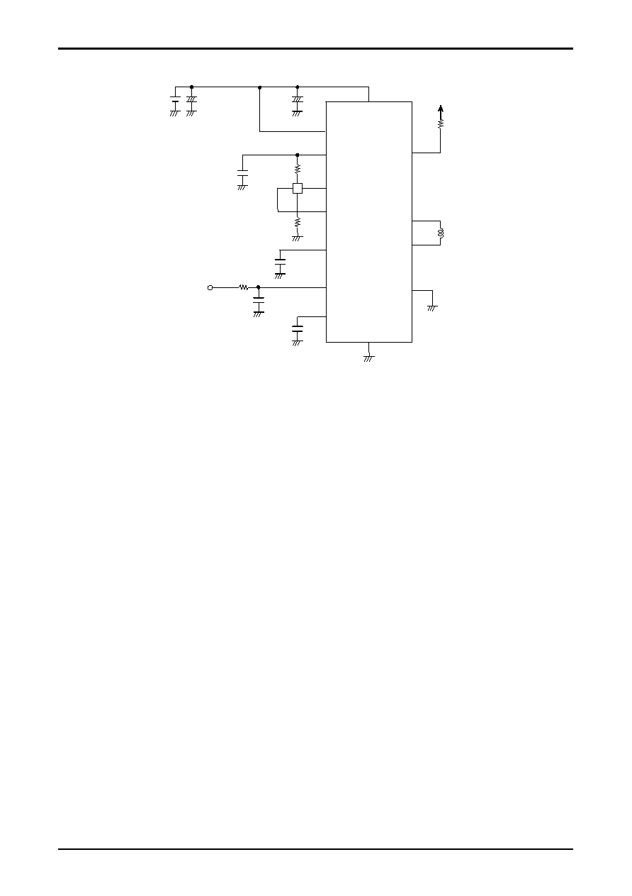
Application Circuit Example 1 (12V single power supply)
P-GND
VM
FG
OUT1
OUT2
CT = 0.47 to 1
μF
CT
VCONT
IN+
IN-
H
5VREG
CPWM
VCC
S-GND
*2
*3
*5
CM
*4
CP = 100pF
CV
*1
*6
*7
CR = 0.1
μF
*8
*1. Power supply and ground lines
VM and P-GND are the motor power supply system and VCC and S-GND are the control circuit power supply system.
These two systems should be formed from separate lines and the control system external components should be connected to
S-GND.
*2. Regeneration power supply stabilization capacitor
This capacitor provides power supply stabilization for both PWM drive and kickback absorption. Since large switching currents
will occur and the power supply line level is easily disrupted, an adequately large capacitor must be used for the CM capacitor.
Since this IC adopts a technique in which switching is performed by the high side transistor and regeneration is handled by the
low side transistor, the pattern connecting CM to VM and P-GND must be as wide and as short as possible.
*3. Hall sensor input
Lines that are as short as possible must be used to prevent noise from entering the system. The Hall sensor input circuit consists
of a comparator with hysteresis (20mV). We recommend that the Hall sensor input level be at least three times this hysteresis, i.e.
at least 60mV.
*4. PWM oscillator frequency setting capacitor
If a value of 100pF is used for CP, the oscillator frequency will be f = 25kHz, and this will be the basic frequency of the PWM
signal.
*5. Lock protection and automatic recovery circuit time constant setting capacitor
If a value of 0.47F is used for CT, this system will operate with an on time of 0.5s and off time of 2.5s when the rotor position
is constrained (locked). This reduces heat generation in the IC and in the motor coils.
If the motor is turning, then the CT pin capacitor will be discharged by the rotation pulses.
If the motor is physically constrained from turning, the rotation pulses will no longer discharge the capacitor, and the CT pin
voltage will rise to VCT1. This will turn off the high side output and stop motor drive. Periodically, the LB11965M will apply a
restart, and thus will iterate a lock protection/automatic recovery cycle while the motor is constrained. When the constraint is
released, the motor will start turning again by the LB11965M's restart mode operation.
*6. FG output
This is an open collector output, and a rotation count detection function can be implemented using this FG output, which
corresponds to the phase switching.
This pin must be left open if unused.
*7. 5VREG line
The capacitor CR must be inserted if fluctuations appear on the 5V line. The current supply capacity of the Hall sensor bias level
is up to a maximum of 10mA.
相关PDF资料 |
PDF描述 |
|---|---|
| LB11985H | BRUSHLESS DC MOTOR CONTROLLER, 1.5 A, PDSO28 |
| LB11988H | BRUSHLESS DC MOTOR CONTROLLER, 1.3 A, PDSO28 |
| LB11995H | DISK DRIVE MOTOR CONTROLLER, 1.3 A, PDSO28 |
| LB11995 | DISK DRIVE MOTOR CONTROLLER, 1.3 A, PDSO24 |
| LB1256 | SPECIALTY ANALOG CIRCUIT, PDIP18 |
相关代理商/技术参数 |
参数描述 |
|---|---|
| LB11966M | 制造商:SANYO 制造商全称:Sanyo Semicon Device 功能描述:2-phase Half-Wave Driver |
| LB11967V | 制造商:ONSEMI 制造商全称:ON Semiconductor 功能描述:For Variable Speed Fan Motor Single-Phase Full-Wave Pre-Driver |
| LB11967V-MPB-E | 功能描述:马达/运动/点火控制器和驱动器 RoHS:否 制造商:STMicroelectronics 产品:Stepper Motor Controllers / Drivers 类型:2 Phase Stepper Motor Driver 工作电源电压:8 V to 45 V 电源电流:0.5 mA 工作温度:- 25 C to + 125 C 安装风格:SMD/SMT 封装 / 箱体:HTSSOP-28 封装:Tube |
| LB11967V-MPB-H | 功能描述:马达/运动/点火控制器和驱动器 RoHS:否 制造商:STMicroelectronics 产品:Stepper Motor Controllers / Drivers 类型:2 Phase Stepper Motor Driver 工作电源电压:8 V to 45 V 电源电流:0.5 mA 工作温度:- 25 C to + 125 C 安装风格:SMD/SMT 封装 / 箱体:HTSSOP-28 封装:Tube |
| LB11967V-TLM-E | 功能描述:马达/运动/点火控制器和驱动器 RoHS:否 制造商:STMicroelectronics 产品:Stepper Motor Controllers / Drivers 类型:2 Phase Stepper Motor Driver 工作电源电压:8 V to 45 V 电源电流:0.5 mA 工作温度:- 25 C to + 125 C 安装风格:SMD/SMT 封装 / 箱体:HTSSOP-28 封装:Tube |
发布紧急采购,3分钟左右您将得到回复。