- 您现在的位置:买卖IC网 > PDF目录30728 > LB1816 SPECIALTY CONSUMER CIRCUIT, PDIP28 PDF资料下载
参数资料
| 型号: | LB1816 |
| 元件分类: | 消费家电 |
| 英文描述: | SPECIALTY CONSUMER CIRCUIT, PDIP28 |
| 封装: | 0.500 INCH, DIP-28 |
| 文件页数: | 7/8页 |
| 文件大小: | 98K |
| 代理商: | LB1816 |
LB1816
No.4626-7/8
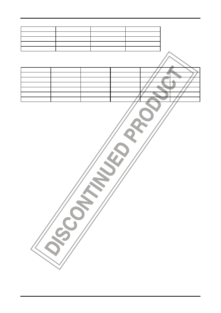
External Component Values (reference values)
Xtal (MHz)
C1 (pF)
C2 (pF)
R (k
Ω)
3 to 4
39
82
0.82
4 to 5
39
82
1.0
5 to 7
39
47
1.5
7 to 10
39
27
2.0
The crystal used must have a fundamental frequency fO impedance to 3fO impedance ratio of 1:5 or greater.
Three-phase Logic Truth Table (the rotation is in one direction only)
H1
H2
H3
OUT1
OUT2
OUT3
H
L
H
L
H
M
H
L
M
H
L
M
L
H
L
H
L
H
L
M
L
H
M
L
H
M
H
L
H1 to H3
OUT1 to OUT3
H: H+ > H-
H: Source
L: H+ < H-
L: Sink
Usage Notes
1. Position detector circuit (Hall device input circuit)
The position detection circuit consists of a differential amplifier, and will operate if a differential input of 30mVp-p
(minimum) is provided. However, an input of 100mVp-p or more is desirable from the standpoint of noise and other
problems.
The input DC level must be within the following common-mode input voltage ranges: H1: 1.5V to (VCC - 1.0) V;
H2: 0.8V to (VCC - 3.0) V; H3: 1.5V to (VCC - 1.7) V.
2. Current limiter circuit
The current limiter operates by holding the sink side transistor in an unsaturated state.
The current limit level can be calculated using the following formula.
I = VCS/Rf
Where: VCS is 0.8V typ, Rf = The value of the resistor between pin 11 and ground
3. FG input
The speed signal FG from the motor is first amplified by the FG amplifier and then converted to a pulse signal by the
Schmitt comparator used to control speed of the motor. The Schmitt comparator has a hysteresis width of 120mV typ.
(240mV max). This means that operations will be performed provided that the gain is set in such a way that the
amplitude of the FG amplifier output is 240mV or higher, but it desirable if the gain is set so that this amplitude is 1V
or more during constant-speed rotation when the lock pull-in, effects of noise, etc. are taken into consideration.
Resistors R8 and R9 provide the resistance that determines the FG amplifier gain, and G = R9/R8 defines the DC gain.
The FG amplifier must be provided with the frequency response by C10 and C11.
4. Reference signal input circuit
4-1. Internal clock mode (crystal oscillator)
The value of the external components associated with the crystal oscillator must be set up according to the
frequency of the oscillator. (See page 7 for the reference value). To avoid trouble with the oscillation circuit,
confirm the oscillator and the component values (C and R) with oscillator’s manufacturer.
4-2. External clock mode
Use the external circuit shown on page 6 to input the clock signal when controlling the motor speed using a
reference signal with the same frequency as FG.
相关PDF资料 |
PDF描述 |
|---|---|
| LB1906CL | STEPPER MOTOR CONTROLLER, 0.1 A, DSO10 |
| LB1933M | STEPPER MOTOR CONTROLLER, 1 A, PDSO14 |
| LB1933M | STEPPER MOTOR CONTROLLER, 1 A, PDSO14 |
| LB1939T | STEPPER MOTOR CONTROLLER, 0.4 A, PDSO20 |
| LB1981V | BRUSHLESS DC MOTOR CONTROLLER, 1 A, PDSO30 |
相关代理商/技术参数 |
参数描述 |
|---|---|
| LB1817M | 制造商:SANYO 制造商全称:Sanyo Semicon Device 功能描述:FDD Spindle Motor Driver |
| LB1817W | 制造商:未知厂家 制造商全称:未知厂家 功能描述:DC Motor Controller/Driver |
| LB1820 | 制造商:SANYO 制造商全称:Sanyo Semicon Device 功能描述:Office Automation-Use 3-Phase Brushless Motor Driver |
| LB1821 | 制造商:SANYO 制造商全称:Sanyo Semicon Device 功能描述:Power Brushless Motor Pre-Driver IC for OA Equipment |
| LB1821M | 制造商:SANYO 制造商全称:Sanyo Semicon Device 功能描述:Power Brushless Motor Pre-Driver IC for OA Equipment |
发布紧急采购,3分钟左右您将得到回复。