- 您现在的位置:买卖IC网 > PDF目录30736 > LC78631E SPECIALTY CONSUMER CIRCUIT, PQFP80 PDF资料下载
参数资料
| 型号: | LC78631E |
| 元件分类: | 消费家电 |
| 英文描述: | SPECIALTY CONSUMER CIRCUIT, PQFP80 |
| 封装: | QFP-80 |
| 文件页数: | 3/34页 |
| 文件大小: | 502K |
| 代理商: | LC78631E |
第1页第2页当前第3页第4页第5页第6页第7页第8页第9页第10页第11页第12页第13页第14页第15页第16页第17页第18页第19页第20页第21页第22页第23页第24页第25页第26页第27页第28页第29页第30页第31页第32页第33页第34页
No. 5342-11/34
LC78631E
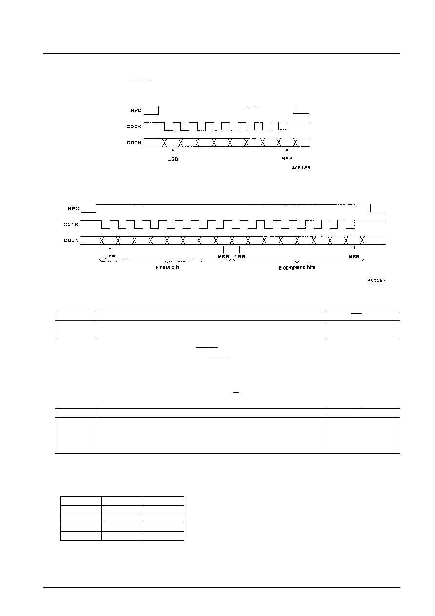
4. Command input
An external controller can execute LC78631E instructions by setting RWC high and inputting commands to COIN in
synchronization with the CQCK clock. Commands are executed on the fall of the RWC signal.
Single-byte commands
Two-byte commands
Command noise reduction
This command can reduce the noise on the CQCK clock signal. While this is effective for noise pulses under
500 ns, the use of this function requires that the CQCK timings tWL, tWH, and tSU (see Figure 1 and 2) be set to
1 s or longer.
5. CLV servo circuit
CLV servo circuit; Pin 13: CLV+, pin 14: CLV–, pin 15: V/P
The CLV+ signal causes the disc to accelerate in the forward direction, and CLV– causes the disc to decelerate. The
microcontroller can select one of four modes: accelerate, decelerate, CLV, and stop. The table below lists the states
of the CLV+ and CLV– pins in each of these modes.
Note: The CLV servo control commands only set the TOFF pin low during CLV mode. That pin will be at the high
level at all other times. Thus controlling the TOFF pin with microcontroller commands is only possible in
CLV mode.
Code
Command
RES = low
$EF
COMMAND INPUT NOISE REDUCTION MODE
$EE
CLEAR THE ABOVE MODE
q
Code
Command
RES = low
$04
DISC MOTOR START (accelerate)
$05
DISC MOTOR CLV (CLV)
$06
DISC MOTOR BRAKE (decelerate)
$07
DISC MOTOR STOP (stop)
q
Mode
CLV+
CLV–
Accelerate
High
Low
Decelerate
Low
High
CLV
Pulse output
Stop
Low
相关PDF资料 |
PDF描述 |
|---|---|
| LC78637E | SPECIALTY CONSUMER CIRCUIT, PQFP80 |
| LC78647NT | SPECIALTY CONSUMER CIRCUIT, PQFP100 |
| LC78648E | SPECIALTY CONSUMER CIRCUIT, PQFP80 |
| LC78681E | SPECIALTY CONSUMER CIRCUIT, PQFP64 |
| LC78681KE-L | SPECIALTY CONSUMER CIRCUIT, PQFP64 |
相关代理商/技术参数 |
参数描述 |
|---|---|
| LC78632 | 制造商:SANYO 制造商全称:Sanyo Semicon Device 功能描述:Compact Disk Player DSP |
| LC78632RE | 制造商:SANYO 制造商全称:Sanyo Semicon Device 功能描述:Compact Disk Player DSP |
| LC78637E-E | 制造商:ON Semiconductor 功能描述: |
| LC7863KA | 制造商:未知厂家 制造商全称:未知厂家 功能描述: |
| LC78641E | 制造商:未知厂家 制造商全称:未知厂家 功能描述:CD-Player Processor/Controller |
发布紧急采购,3分钟左右您将得到回复。