- 您现在的位置:买卖IC网 > PDF目录19049 > LF10BP-T01 (Hirose Electric Co Ltd)TOOL JIG ASSEM FOR LF10 PLUG PDF资料下载
参数资料
| 型号: | LF10BP-T01 |
| 厂商: | Hirose Electric Co Ltd |
| 文件页数: | 10/16页 |
| 文件大小: | 0K |
| 描述: | TOOL JIG ASSEM FOR LF10 PLUG |
| 产品培训模块: | HRS Waterproof Connector LF Waterproof Metal Circular Connector |
| 标准包装: | 1 |
| 系列: | LF10 |
| 附件类型: | 夹具组件 |
| 产品目录页面: | 413 (CN2011-ZH PDF) |
| 其它名称: | *LF10BP-T01 H9911 |
�� �
�
�LF� Series� q� this� catalog� is� reference� only.� Please�
�The� product� information� Miniature� Waterproof� Shielded� Connectors� request� the� Engineering� Drawing� for� the� most� current� and� accurate� design� information.�
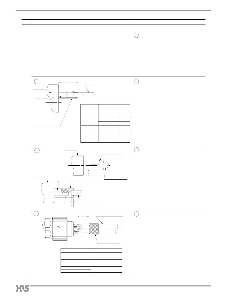
�No.�
�4�
�Illustration�
�Operation�
�Soldering�
�1�
�Soldering� conditions�
�Soldering� iron� tip� temperature:� 350±10?�
�Soldering� time:� within� 5� sec.�
�Notes�
�(1)� Assure� that� the� solder� compound� is�
�sufficiently� melted� on� the� soldering� iron� tip.�
�(2)� When� applying,� make� sure� that� the� solder� will�
�flow� correctly� at� all� the� contact� surfaces�
�between� the� conductor� and� the� contact.�
�2�
�–1�
�Cmm�
�Wire�
�2�
�–� 1� 6,� 12,� 20,� 11� (No.1~7)� Conductors�
�Insulator�
�Contact�
�(1)� Place� a� heat-shrink� tubing� (inside� diameter� of�
�1.1� mm� min.)� over� every� other� wire.�
�Perform� the� soldering� of� the� contact� and� the�
�C� mm�
�Heat-shrink� tubing�
�Table� 3� Heat� shrink� tubing� Dimensions�
�Number� of� Number� of�
�Conductors� contacts�
�6� 1� to� 6� 4�
�1� to� 9� 4�
�12�
�10� to� 12� 6�
�(2)� conductor,� with� the� wire’s� insulation� touching�
�the� contact� as� shown.�
�After� soldering,� slide� the� heat� shrink� tubing�
�(3)� over� the� soldered� joint� and� shrink� it.� The�
�tubing� should� touch� the� insulator� as� shown.�
�20�
�11�
�1� to� 5,16� to� 20�
�6� to� 15�
�1� to� 4�
�5� to� 7�
�4�
�6�
�6�
�4�
�2�
�–2�
�Insulator�
�Insulator� wall�
�2� –� 2� 3,� 4,� 11� (No.A~D)� Conductors�
�(1)� Perform� the� soldering� of� the� contact� and� the�
�conductor,� with� the� wire’s� insulation� touching�
�the� contact� as� illustrated.�
�(2)� When� soldering,� to� maintain� the� insulation�
�Insulator�
�Contact�
�Contact� Insulator� wall�
�Wire� insulation�
�between� adjacent� contacts.� Make� sure� that�
�the� wire’s� insulation� remains� below� the� edge�
�of� the� insulator’s� wall� 0.5� mm� min.,� as�
�illustrated.�
�Wire� insulation�
�Solder�
�0.5� mm� min.�
�3�
�D�
�Cable outer jacket�
�3�
�After� the� soldering,� keep� a� distance� of� D�
�between� the� contact� end� and� the� cable’s�
�outer� jacket� as� illustrated.�
�Note�
�10�
�Table� 4.� Wire� Dimensions�
�Number� of� Conductors�
�3�
�6�
�4�
�12�
�11�
�20�
�Shielding� mesh�
�(Folded� back)�
�D� mm�
�6� to� 7�
�10� to� 11�
�13� to� 14�
�18� to� 19�
�The� distance� of� D� is� required� in� order� to�
�assure� correct� assembly� of� the� backshell.�
�相关PDF资料 |
PDF描述 |
|---|---|
| LF07BP-T01 | TOOL JIG ASSEM FOR LF07 PLUG |
| A3C-3004 | TIGHTENING TOOL |
| 140-0000-958 | TOOL BODY SOLDERING FOR .086 |
| 164TL5 | SWITCH UNIT ALT ILLUM RECT |
| 164SL5 | SWITCH UNIT ALT ILLUM SQ |
相关代理商/技术参数 |
参数描述 |
|---|---|
| LF10C32C1 | 制造商:未知厂家 制造商全称:未知厂家 功能描述:1.2mm 2 Pin Ceramic Surface Mount Crystal |
| LF10C32E1 | 制造商:未知厂家 制造商全称:未知厂家 功能描述:1.2mm 2 Pin Ceramic Surface Mount Crystal |
| LF10C32F1 | 制造商:未知厂家 制造商全称:未知厂家 功能描述:1.2mm 2 Pin Ceramic Surface Mount Crystal |
| LF10C8 | 制造商:Pulse 功能描述:TRANSFORMERS - Rail/Tube |
| LF10C9 | 制造商:Pulse Electronics Corporation 功能描述:TRANSFORMERS - Rail/Tube |
发布紧急采购,3分钟左右您将得到回复。