- 您现在的位置:买卖IC网 > PDF目录378649 > LF43168QC30 (LOGIC DEVICES INC) Dual 8-Tap FIR Filter PDF资料下载
参数资料
| 型号: | LF43168QC30 |
| 厂商: | LOGIC DEVICES INC |
| 元件分类: | 数字信号处理外设 |
| 英文描述: | Dual 8-Tap FIR Filter |
| 中文描述: | 10-BIT, DSP-DIGITAL FILTER, PQFP100 |
| 封装: | PLASTIC, QFP-100 |
| 文件页数: | 8/16页 |
| 文件大小: | 184K |
| 代理商: | LF43168QC30 |
DEVICES INCORPORATED
LF43168
Dual 8-Tap FIR Filter
8
Video Imaging Products
03/28/2000–LDS.43168-H
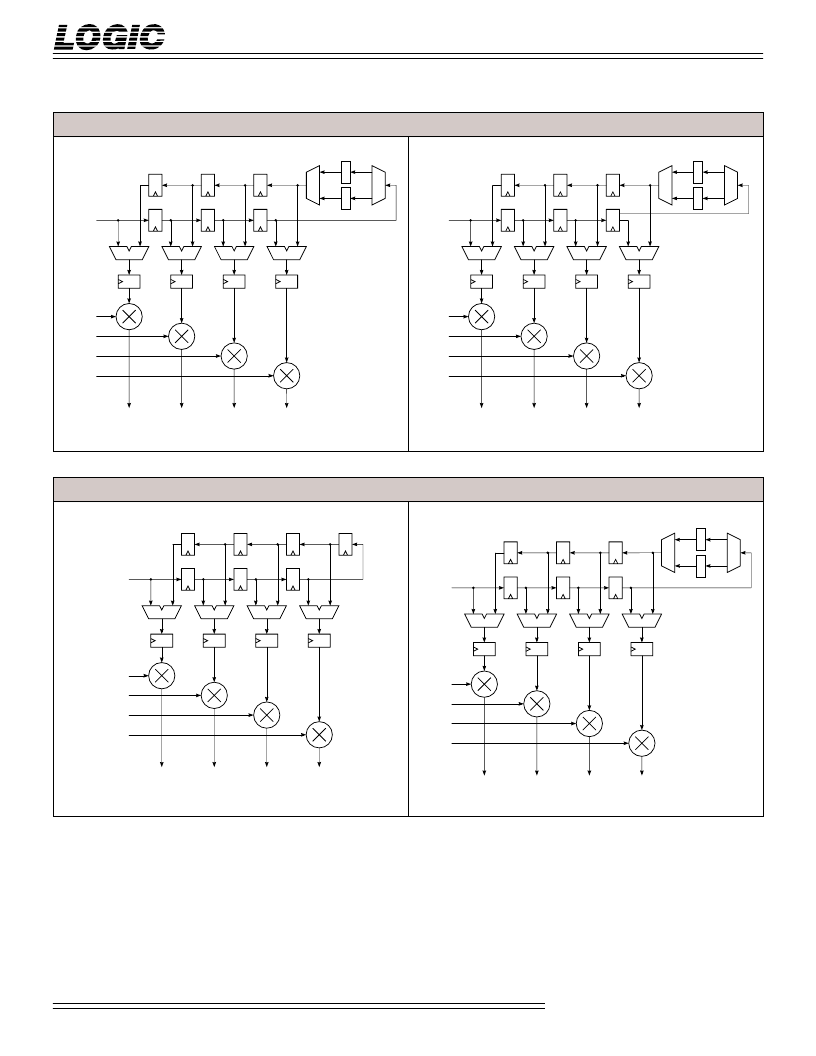
Figure 5 shows the two possible
configurations when the device is
programmed as a decimating, even-
symmetric coefficient filter. The delay
length of the decimation registers will
be equal to the decimation factor that
the device is programmed for. Since
only four coefficients (effectively
eight) can be sent to the filter multipli-
ers on a clock cycle, it may be neces-
sary (depending on the coefficient set)
to change the coefficients fed to the
multipliers on different CLK cycles for
filters with more than eight taps. Note
that for the odd-tap filter, the middle
coefficient of the coefficient set must
be divided by two to get the correct
result.
Odd-Symmetric Coefficient Filters
Figure 6 shows the two possible
configurations when the device is
programmed for odd-symmetric
coefficients. Note that odd-tap, odd-
symmetric coefficient filters are not
possible.
F
IGURE
5.
D
ECIMATING
, E
VEN
-S
YMMETRIC
C
OEFFICIENT
F
ILTER
C
ONFIGURATIONS
COEF 0
COEF 1
COEF 2
COEF 3
B + A
A
B
B + A
A
B
B + A
A
B
B + A
A
B
DATA IN
M
L
L
D
N
N
N
N
N
N
N = Delay Length (Decimation Factor)
EVEN-TAP FILTER
COEF 0
COEF 1
COEF 2
COEF 3
B + A
A
B
B + A
A
B
B + A
A
B
B + A
A
B
DATA IN
M
L
L
D
N
N
N
N
N
N
N = Delay Length (Decimation Factor)
Delay Stage N – 1 Output
ODD-TAP FILTER
F
IGURE
6.
O
DD
-S
YMMETRIC
C
OEFFICIENT
F
ILTER
C
ONFIGURATIONS
COEF 0
COEF 1
COEF 2
COEF 3
B – A
A
B
B – A
A
B
B – A
A
B
B – A
A
B
DATA IN
EVEN-TAP FILTER (NO DECIMATION)
COEF 0
COEF 1
COEF 2
COEF 3
B – A
A
B
B – A
A
B
B – A
A
B
B – A
A
B
DATA IN
M
L
L
D
N
N
N
N
N
N
N = Delay Length (Decimation Factor)
DECIMATING, EVEN-TAP FILTER
相关PDF资料 |
PDF描述 |
|---|---|
| LF43891JC40 | 9 x 9-bit Digital Filter |
| LF43891 | 9 x 9-bit Digital Filter |
| LF43891JC33 | 9 x 9-bit Digital Filter |
| LF48908QC25 | Two Dimensional Convolver |
| LF48908QC31 | Two Dimensional Convolver |
相关代理商/技术参数 |
参数描述 |
|---|---|
| LF43168QI15 | 制造商:未知厂家 制造商全称:未知厂家 功能描述:Digital Filter |
| LF43168QI22 | 制造商:未知厂家 制造商全称:未知厂家 功能描述:Digital Filter |
| LF43168QI30 | 制造商:未知厂家 制造商全称:未知厂家 功能描述:Digital Filter |
| LF-432 | 制造商:SIRENZA 制造商全称:SIRENZA 功能描述:Wideband RF/Pulse Transformers .1-50 MHz/.01-25 MHz |
| LF43881 | 制造商:LOGIC 制造商全称:LOGIC 功能描述:8 x 8-bit Digital Filter |
发布紧急采购,3分钟左右您将得到回复。