- 您现在的位置:买卖IC网 > PDF目录44530 > LM1572MTCX-3.3/NOPB (NATIONAL SEMICONDUCTOR CORP) 3.2 A SWITCHING REGULATOR, 570 kHz SWITCHING FREQ-MAX, PDSO16 PDF资料下载
参数资料
| 型号: | LM1572MTCX-3.3/NOPB |
| 厂商: | NATIONAL SEMICONDUCTOR CORP |
| 元件分类: | 稳压器 |
| 英文描述: | 3.2 A SWITCHING REGULATOR, 570 kHz SWITCHING FREQ-MAX, PDSO16 |
| 封装: | TSSOP-16 |
| 文件页数: | 4/17页 |
| 文件大小: | 583K |
| 代理商: | LM1572MTCX-3.3/NOPB |
Application Information (Continued)
Output Capacitor Selection
In voltage mode control, the esr of the output capacitor plays
an important role in the feedback loop. Therefore in such
cases, it is usually cautioned against reducing the esr too
much. But keeping the esr high enough to guarantee loop
stability has several ’side-effects’: it prevents the use of
ceramic capacitors at the output, it also keeps the dissipation
in the output capacitor ’high’ (since this is I
P
2*esr), and it also
keeps the output voltage ripple ’high’ (which too is propor-
tional to esr). Note that a post LC filter therefore becomes
necessary with voltage mode controllers, if really low output
voltage ripple is required.
With current mode control, the feedback loop is different,
and so the output esr can be reduced significantly. Therefore
the main criterion for selection of the output capacitor is
based on the acceptable output voltage ripple. In the ex-
ample, assuming that ±75mV of ripple is acceptable (i.e.
150mV peak to peak), the peak to peak current is
I
PP =IOr
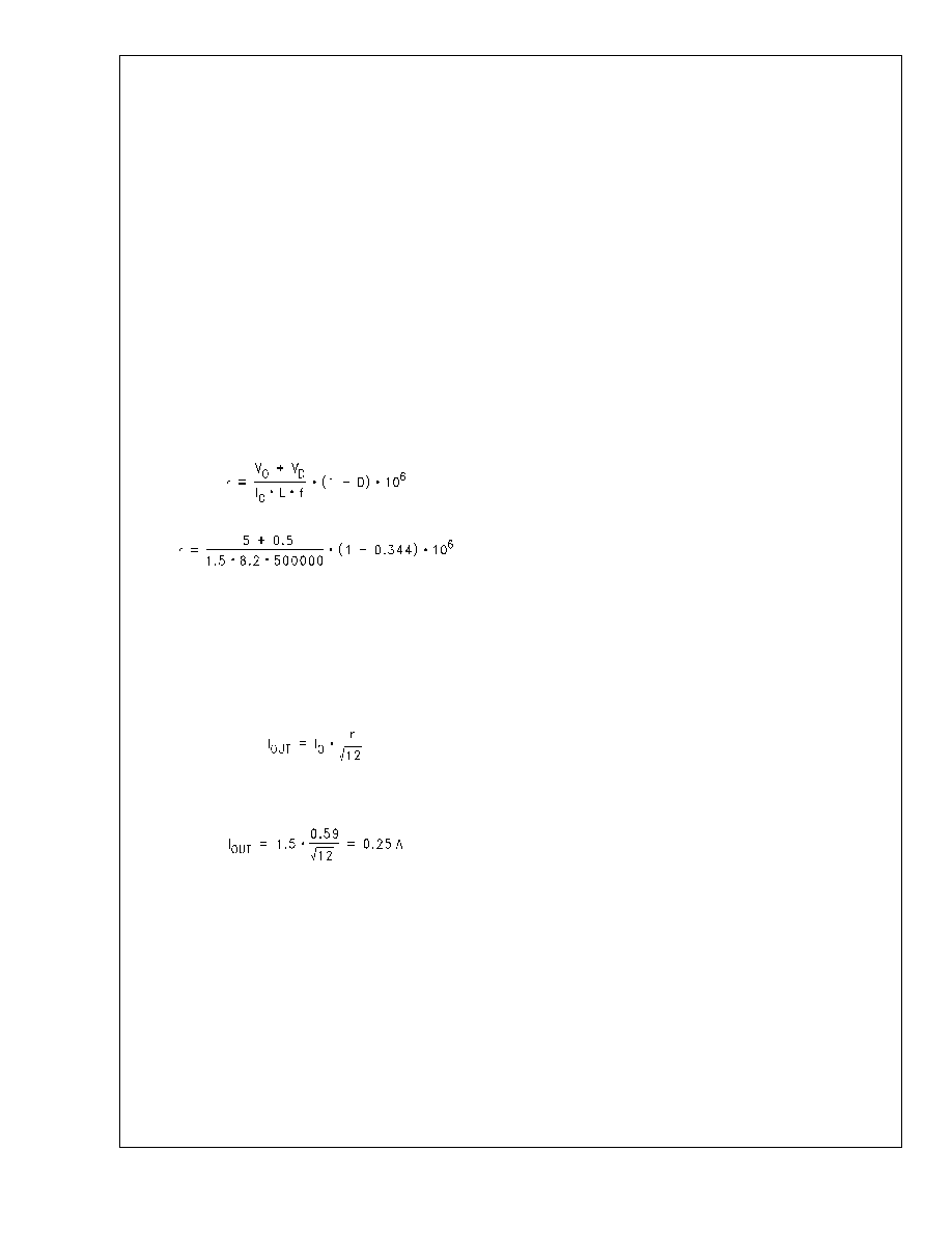
The worst case condition for this parameter is at minimum
duty cycle (max input). At this point, with the chosen inductor
r = 0.59
So peak to peak current is
I
PP = 1.5 0.59 = 0.88A
For a maximum 150mV ripple the esr must be less than
esr = 0.150/0.88 = 0.17
The RMS current capability should also be checked. The
RMS output current is
The worst case condition for this parameter is at highest
input voltage. So
Therefore a close fit is tantalum 100F/10V TPS series AVX
capacitor, Part Number TPSY010K010S0150, esr of 0.15
,
rated for RMS current 0.822A at 85C. An alternative is
Panasonic surface mount aluminum 330F/10V FK series,
Part Number EEVFK1A331P, esr of 0.16
, rated for RMS
0.6A at 105C. Note that the esr (and allowed output voltage
ripple) played the dominant rule in the selection here. If very
low output ripple is demanded, it would point in the direction
of larger and larger capacitances. However, it must be kept
in mind that a very large output capacitance can lead to
startup problems, because of the huge charging current (and
its duration). The choice of tantalum at the output will permit
a much lower capacitance to be used, which leads to a
smaller energy inrush (12*C*V
2) and no startup problems.
Therefore when using ’low cost’ aluminum capacitors at the
output, (which always end up having a larger capacitance
than tantalums for the same esr), softstart is recommended
so as to prevent startup problems.In addition, very low esr
(irrespective of whether capacitor is aluminimum, tantalum
etc.), can lead to loop instability and therefore a Bode plot is
recommended to ensure adequate phase margin.
Sequencing
This section may be skipped if the SD pin is floating, or tied
high. It is of concern only if the Designer intends to use the
Shutdown pin in an active manner.
The following scenario explains the situation: if the input
voltage is applied and the converter has been running for
some time (SD pin high), the bootstrap capacitor is (as is
normal) charged up to about 5V. Now if the input is discon-
nected, and then reconnected immediately, while holding the
SD pin low, the following can happen: the output which is
expected to be zero, may go ’high’ (no regulation). It returns
to regulation only when the SD pin is taken high (over
2.38V). This mode occurs only under the above set of con-
ditions, and only if the applied input ramp has an extremely
high slope. Then the dV/dt of the ramp injects stray charge
through the Drain-Gate capacitance of the internal Fet driv-
ers, causing the gate voltage to go high, and may eventually
cause the switching Fet to turn on spuriously. The switch will
then stay in full conduction, till the next level shift command
comes from the SD pin. Several options exist so as to avoid
this:
1.
The SD pin must not be held low during the instant that
the reapplied input voltage is ramping up across the
input of the converter.
2.
Or the input dV/dt must be kept low. One way is to
increase the input capacitance (and/or esr), as men-
tioned earlier. Therefore, it is recommended that if the
SD pin is expected to be used actively (not floating or
high), the input capacitor should always be an aluminum
electrolytic. This will automatically lead to a larger ca-
pacitance value and esr, as desired. Further, the oscil-
lations and overshoot at the input, described earlier,
which are also contributory factors to this spurious turn-
on, will also be suppressed.
3.
Or the Bootstrap capacitor must be discharged. Now,
since the voltage across the bootstrap capacitor hap-
pens to be the supply for the internal driver, if this
capacitor is discharged before the input is reapplied,
there will be no problem: no supply, no drive! To imple-
ment this, it is recommended that the bootstrap capaci-
tance used is reduced to 0.01F and in addition, a
1M-4.7M resistor placed from the bootstrap pin to
ground. This provides a discharge path for the bootstrap
capacitor. The RC time constant is about 10-50ms, and
so a ’wait period’ of like amount is recommended before
input power is reapplied. This will allow sufficient time for
the bootstrap capacitor to discharge, and the spurious
turn-on will be prevented.
Overload Protection
The LM1572 incorporates a useful protection feature called
’frequency foldback’. When the voltage on the feedback
node starts falling to zero below a certain threshold, the IC
commands a progressive reduction in switching frequency
from 500kHz to 100kHz. The reader is referred to the rel-
evant curve in Typical Performance Characteristics of this
datasheet. The pulse width also decreases to the minimum
width of 300ns (typical). These actions help protect not only
the IC, but also the external power components and the load.
LM1572
www.national.com
12
相关PDF资料 |
PDF描述 |
|---|---|
| LM1572MTC-3.3/NOPB | 3.2 A SWITCHING REGULATOR, 570 kHz SWITCHING FREQ-MAX, PDSO16 |
| LM1572MTC-ADJ/NOPB | 3.2 A SWITCHING REGULATOR, 570 kHz SWITCHING FREQ-MAX, PDSO16 |
| LM1575J-ADJ/883 | 3 A SWITCHING REGULATOR, 58 kHz SWITCHING FREQ-MAX, CDIP16 |
| LM1575J-5.0/883 | 3 A SWITCHING REGULATOR, 58 kHz SWITCHING FREQ-MAX, CDIP16 |
| LM1575J-15/883 | 3 A SWITCHING REGULATOR, 58 kHz SWITCHING FREQ-MAX, CDIP16 |
相关代理商/技术参数 |
参数描述 |
|---|---|
| LM1572MTCX-5.0/NOPB | 功能描述:IC REG BUCK 5V 1.5A 16TSSOP RoHS:是 类别:集成电路 (IC) >> PMIC - 稳压器 - DC DC 开关稳压器 系列:- 产品培训模块:Lead (SnPb) Finish for COTS Obsolescence Mitigation Program 标准包装:1 系列:- 类型:降压(降压) 输出类型:固定 输出数:1 输出电压:3.3V 输入电压:4.5 V ~ 24 V PWM 型:- 频率 - 开关:- 电流 - 输出:125mA 同步整流器:无 工作温度:-40°C ~ 85°C 安装类型:表面贴装 封装/外壳:SOT-23-6 包装:Digi-Reel® 供应商设备封装:SOT-6 其它名称:MAX1836EUT33#TG16DKR |
| LM1572MTCX-ADJ/NOPB | 功能描述:IC REG BUCK ADJ 1.5A 16TSSOP RoHS:是 类别:集成电路 (IC) >> PMIC - 稳压器 - DC DC 开关稳压器 系列:- 产品培训模块:Lead (SnPb) Finish for COTS Obsolescence Mitigation Program 标准包装:1 系列:- 类型:降压(降压) 输出类型:固定 输出数:1 输出电压:3.3V 输入电压:4.5 V ~ 24 V PWM 型:- 频率 - 开关:- 电流 - 输出:125mA 同步整流器:无 工作温度:-40°C ~ 85°C 安装类型:表面贴装 封装/外壳:SOT-23-6 包装:Digi-Reel® 供应商设备封装:SOT-6 其它名称:MAX1836EUT33#TG16DKR |
| LM1575 | 制造商:NSC 制造商全称:National Semiconductor 功能描述:SIMPLE SWITCHER㈢ 1A Step-Down Voltage Regulator |
| LM1575_07 | 制造商:NSC 制造商全称:National Semiconductor 功能描述:SIMPLE SWITCHER㈢ 1A Step-Down Voltage Regulator |
| LM1575-12 | 制造商:NSC 制造商全称:National Semiconductor 功能描述:SIMPLE SWITCHER 1A STEP-DOWN VOLTAGE REGULATOR |
发布紧急采购,3分钟左右您将得到回复。