- 您现在的位置:买卖IC网 > PDF目录240272 > LM1575-5.0MD8 (NATIONAL SEMICONDUCTOR CORP) 3.2 A SWITCHING REGULATOR, 62 kHz SWITCHING FREQ-MAX, UUC PDF资料下载
参数资料
| 型号: | LM1575-5.0MD8 |
| 厂商: | NATIONAL SEMICONDUCTOR CORP |
| 元件分类: | 稳压器 |
| 英文描述: | 3.2 A SWITCHING REGULATOR, 62 kHz SWITCHING FREQ-MAX, UUC |
| 封装: | DIE |
| 文件页数: | 5/40页 |
| 文件大小: | 917K |
| 代理商: | LM1575-5.0MD8 |
第1页第2页第3页第4页当前第5页第6页第7页第8页第9页第10页第11页第12页第13页第14页第15页第16页第17页第18页第19页第20页第21页第22页第23页第24页第25页第26页第27页第28页第29页第30页第31页第32页第33页第34页第35页第36页第37页第38页第39页第40页
INDUCTOR VALUE SELECTION GUIDES (For Continuous Mode Operation) (Continued)
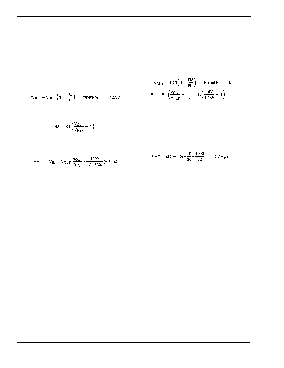
PROCEDURE (Adjustable Output Voltage Versions)
EXAMPLE (Adjustable Output Voltage Versions)
Given:
V
OUT = Regulated Output Voltage
V
IN(Max) = Maximum Input Voltage
I
LOAD(Max) = Maximum Load Current
F = Switching Frequency
(Fixed at 52 kHz)
Given:
V
OUT = 10V
V
IN(Max) = 25V
I
LOAD(Max) = 1A
F=52 kHz
1. Programming Output Voltage
(Selecting R1 and R2, as
shown in Figure 2 )
Use the following formula to select the appropriate resistor
values.
R
1 can be between 1k and 5k. (For best temperature coeffi-
cient and stability with time, use 1% metal film resistors)
1.Programming Output Voltage
(Selecting R1 and R2)
R2 = 1k (8.13 1) = 7.13k, closest 1% value is 7.15k
2. Inductor Selection (L1)
A. Calculate the inductor Volt
microsecond constant,
E
T(V s), from the following formula:
B. Use the E
T value from the previous formula and match
it with the E
T number on the vertical axis of the Inductor
Value Selection Guide shown in
C. On the horizontal axis, select the maximum load current.
D. Identify the inductance region intersected by the E
T
value and the maximum load current value, and note the
inductor code for that region.
E. Identify the inductor value from the inductor code, and
select an appropriate inductor from the table shown in
9. Part numbers are listed for three inductor manufacturers.
The inductor chosen must be rated for operation at the
LM2575 switching frequency (52 kHz) and for a current rating
of 1.15 x I
LOAD. For additional inductor information, see the
inductor section in the application hints section of this data
sheet.
2. Inductor Selection (L1)
A. Calculate E
T(V s)
B. E
T= 115 V s
C. I
LOAD(Max) = 1A
D. Inductance Region = H470
E. Inductor Value = 470 H
Choose from AIE part #430-0634,
Pulse
Engineering
part
#PE-53118,
or
Renco
part
#RL-1961.
LM1575/LM2575/LM2575HV
www.national.com
13
相关PDF资料 |
PDF描述 |
|---|---|
| LM4050BIX3-2.5+T | 1-OUTPUT TWO TERM VOLTAGE REFERENCE, 2.5 V, PDSO3 |
| LPC5S | 1-OUTPUT 50 W DC-DC REG PWR SUPPLY MODULE |
| LPC9D | 2-OUTPUT 65 W DC-DC REG PWR SUPPLY MODULE |
| LMB5SP | 1-OUTPUT 50 W DC-DC REG PWR SUPPLY MODULE |
| LM4040BIZ-8.2X | 1-OUTPUT TWO TERM VOLTAGE REFERENCE, 8.192 V, PBCY3 |
相关代理商/技术参数 |
参数描述 |
|---|---|
| LM1575AK | 制造商:未知厂家 制造商全称:未知厂家 功能描述:Voltage-Mode SMPS Controller |
| LM1575HVK-12/883 | 制造商:未知厂家 制造商全称:未知厂家 功能描述:Voltage-Mode SMPS Controller |
| LM1575HVK12/883QF | 制造商:Rochester Electronics LLC 功能描述:- Bulk 制造商:Texas Instruments 功能描述: |
| LM1575HVK-15/883 | 制造商:未知厂家 制造商全称:未知厂家 功能描述:Voltage-Mode SMPS Controller |
| LM1575HVK-3.3/883 | 制造商:未知厂家 制造商全称:未知厂家 功能描述:Voltage-Mode SMPS Controller |
发布紧急采购,3分钟左右您将得到回复。