- 您现在的位置:买卖IC网 > PDF目录30744 > LM1894MWC (NATIONAL SEMICONDUCTOR CORP) SPECIALTY CONSUMER CIRCUIT, UUC PDF资料下载
参数资料
| 型号: | LM1894MWC |
| 厂商: | NATIONAL SEMICONDUCTOR CORP |
| 元件分类: | 消费家电 |
| 英文描述: | SPECIALTY CONSUMER CIRCUIT, UUC |
| 封装: | WAFER |
| 文件页数: | 10/12页 |
| 文件大小: | 345K |
| 代理商: | LM1894MWC |
Application Hints
The DNR system should always be placed before tone and
volume controls as shown in
Figure 1. This is because any
adjustment of these controls would alter the noise floor seen
by the DNR control path. The sensitivity resistors R1 and R2
may need to be switched with the input selector, depending
on the noise floors of different sources, i.e., tape, FM, phono.
To determine the value of R1 and R2 in a tape system for
instance; apply tape noise (no program material) and adjust
the ratio of R1 and R2 to open slightly the bandwidth of the
main signal path. This can easily be done by viewing the
capacitor voltage of pin 10 with an oscilloscope, or by using
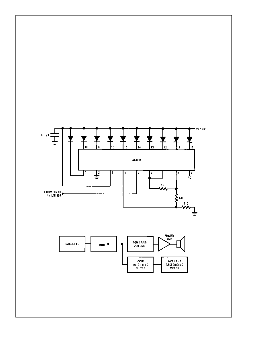
the circuit of
Figure 5. This circuit gives an LED display of the
voltage on the peak detector capacitor. Adjust the values of
R1 and R2 (their sum is always 1 k
) to light the LEDs of pin
1 and pin 18. The LED bar graph does not indicate signal
level, but rather instantaneous bandwidth of the two filters; it
should not be used as a signal-level indicator. For greater
flexibility in setting the bandwidth sensitivity, R1 and R2
could be replaced bya1k
potentiometer.
To change the minimum and maximum value of bandwidth,
the integrating capacitors, C3 and C12, can be scaled up or
down. Since the bandwidth is inversely proportional to the
capacitance, changing this 0.0039 F capacitor to 0.0033 F
will change the typical bandwidth from 965 Hz–34 kHz to 1.1
kHz–40 kHz. With C3 and C12 set at 0.0033 F, the maxi-
mum bandwidth is typically 34 kHz. A double pole double
throw switch can be used to completely bypass DNR.
The capacitor on pin 10 in conjunction with internal resistors
sets the attack and decay times. The attack time can be
altered by changing the size of C10. Decay times can be
decreased by paralleling a resistor with C10, and increased
by increasing the value of C10.
When measuring the amount of noise reduction of the DNR
system, the frequency response of the cassette should be
flat to 10 kHz. The CCIR weighting network has substantial
gain to 8 kHz and any additional roll-off in the cassette player
will reduce the benefits of DNR noise reduction. A typical
signal-to-noise measurement circuit is shown in
Figure 6.
The DNR system should be switched from maximum band-
width to nominal bandwidth with tape noise as a signal
source.
The
reduction
in
measured
noise
is
the
signal-to-noise ratio improvement.
DS007918-10
FIGURE 5. Bar Graph Display of Peak Detector Voltage
DS007918-11
FIGURE 6. Technique for Measuring S/N Improvement of the DNR System
LM1894
www.national.com
7
相关PDF资料 |
PDF描述 |
|---|---|
| LM1894MT/NOPB | SPECIALTY CONSUMER CIRCUIT, PDSO14 |
| LM1894MTX/NOPB | SPECIALTY CONSUMER CIRCUIT, PDSO14 |
| LM1897N | 2 CHANNEL, AUDIO AMPLIFIER, PDIP16 |
| LM1971-NRE | SPECIALTY CONSUMER CIRCUIT, PDIP8 |
| LM1971MDC | SPECIALTY CONSUMER CIRCUIT, UUC |
相关代理商/技术参数 |
参数描述 |
|---|---|
| LM1894MX | 功能描述:特殊用途放大器 RoHS:否 制造商:Texas Instruments 通道数量:Single 共模抑制比(最小值): 输入补偿电压: 工作电源电压:3 V to 5.5 V 电源电流:5 mA 最大功率耗散: 最大工作温度:+ 70 C 最小工作温度:- 40 C 安装风格:SMD/SMT 封装 / 箱体:QFN-20 封装:Reel |
| LM1894MX/NOPB | 功能描述:特殊用途放大器 RoHS:否 制造商:Texas Instruments 通道数量:Single 共模抑制比(最小值): 输入补偿电压: 工作电源电压:3 V to 5.5 V 电源电流:5 mA 最大功率耗散: 最大工作温度:+ 70 C 最小工作温度:- 40 C 安装风格:SMD/SMT 封装 / 箱体:QFN-20 封装:Reel |
| LM1894N | 制造商:Rochester Electronics LLC 功能描述:- Bulk 制造商:OC White Company 功能描述:Dynamic Noise Reduction System 14-Pin PDIP Rail |
| LM1895 | 制造商:NSC 制造商全称:National Semiconductor 功能描述:AUDIO POWE RAMPLIFIER |
| LM1895N | 制造商:NSC 制造商全称:National Semiconductor 功能描述:AUDIO POWE RAMPLIFIER |
发布紧急采购,3分钟左右您将得到回复。