- 您现在的位置:买卖IC网 > PDF目录30744 > LM1894MWC (NATIONAL SEMICONDUCTOR CORP) SPECIALTY CONSUMER CIRCUIT, UUC PDF资料下载
参数资料
| 型号: | LM1894MWC |
| 厂商: | NATIONAL SEMICONDUCTOR CORP |
| 元件分类: | 消费家电 |
| 英文描述: | SPECIALTY CONSUMER CIRCUIT, UUC |
| 封装: | WAFER |
| 文件页数: | 8/12页 |
| 文件大小: | 345K |
| 代理商: | LM1894MWC |
External Component Guide
(
Figure 1)
Component
Value
Purpose
C1
0.1 F–
100 F
May be part of power supply,
or may be added to suppress
power supply oscillation.
C2, C13
1 F
Blocks DC, pin 2 and pin 13
are at DC potential of V
S/2.
C2, C13 form a low frequency
pole with 20k R
IN.
C14
25 F–
100 F
Improves power supply
rejection.
C3, C12
0.0033 F
Forms integrator with internal
gm block and op amp. Sets
bandwidth conversion gain of
33 Hz/A of gm current.
C4, C11
1 F
Output coupling capacitor.
Output is at DC potential of
V
S/2.
C5
0.1 F
Works with R1 and R2 to
attenuate low frequency
transients which could disturb
control path operation.
C6
0.001 F
Works with input resistance of
pin 6 to form part of control
path frequency weighting.
C8
0.1 F
Combined with L8 and C
L
forms 19 kHz filter for FM
pilot. This is only required in
FM applications (Note 9).
L8, C
L
4.7 mH,
0.015 F
Forms 19 kHz filter for FM
pilot. L8 is Toko coil
CAN-1A185HM (Notes 8, 9).
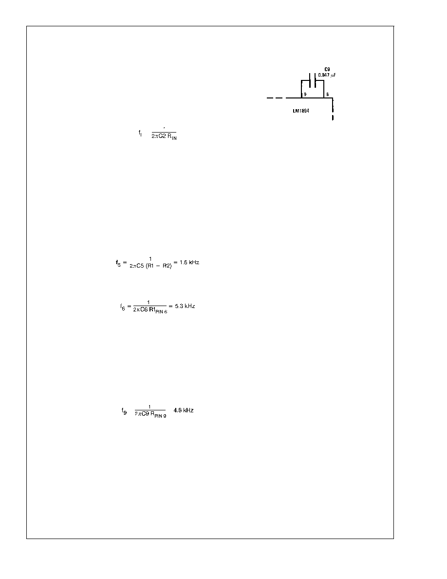
C9
0.047 F
Works with input resistance of
pin 9 to form part of control
path frequency weighting.
C10
1 F
Set attack and decay time of
peak detector.
R1, R2
1 k
Sensitivity resistors set the
noise threshold. Reducing
attentuation causes larger
signals to be peak detected
and larger bandwidth in main
signal path. Total value of R1
+ R2 should equal 1 k
.
R8
100
Forms RC roll-off with C8.
This is only required in FM
applications.
Note 8: Toko America Inc., 1250 Feehanville Drive, Mt. Prospect IL 60056
Note 9: When FM applications are not required, pin 8 and pin 9 hook-up as
follows:
Circuit Operation
The LM1894 has two signal paths, a main signal path and a
bandwidth control path. The main path is an audio low pass
filter comprised of a gm block with a variable current, and an
op amp configured as an integrator. As seen in
Figure 2,DC
feedback constrains the low frequency gain to A
V = 1.
Above the cutoff frequency of the filter, the output decreases
at 6 dB/oct due to the action of the 0.0033 F capacitor.
The purpose of the control paths is to generate a bandwidth
control signal which replicates the ear’s sensitivity to noise in
the presence of a tone. A single control path is used for both
channels to keep the stereo image from wandering. This is
done by adding the right and left channels together in the
summing amplifier of
Figure 2. The R1, R2 resistor divider
adjusts the incoming noise level to open slightly the band-
width of the low pass filter. Control path gain is about 60 dB
and is set by the gain amplifier and peak detector gain. This
large gain is needed to ensure the low pass filter bandwidth
can be opened by very low noise floors. The capacitors
between the summing amplifier output and the peak detector
input determine the frequency weighting as shown in the
typical performance curves. The 1 F capacitor at pin 10, in
conjunction with internal resistors, sets the attack and decay
times. The voltage is converted into a proportional current
which is fed into the gm blocks. The bandwidth sensitivity to
gm current is 33 Hz/A. In FM stereo applications at 19 kHz
pilot filter is inserted between pin 8 and pin 9 as shown in
Figure 1.
Figure 3 is an interesting curve and deserves some discus-
sion. Although the output of the DNR system is a linear
function of input signal, the 3 dB bandwidth is not. This is
due to the non-linear nature of the control path. The DNR
system has a uniform frequency response, but looking at the
3 dB bandwidth on a steady state basis with a single
frequency input can be misleading. It must be remembered
that a single input frequency can only give a single 3 dB
bandwidth and the roll-off from this point must be a smooth
6 dB/oct.
A more accurate evaluation of the frequency response can
be seen in
Figure 4. In this case the main signal path is
frequency swept, while the control path has a constant fre-
quency applied. It can be seen that different control path
frequencies each give a distinctive gain roll-off.
Psychoacoustic Basics
The dynamic noise reduction system is a low pass filter that
has a variable bandwidth of 1 kHz to 30 kHz, dependent on
music spectrum. The DNR system operates on three prin-
ciples of psychoacoustics.
1. White noise can mask pure tones. The total noise energy
required to mask a pure tone must equal the energy of the
tone itself. Within certain limits, the wider the band of mask-
DS007918-6
LM1894
www.national.com
5
相关PDF资料 |
PDF描述 |
|---|---|
| LM1894MT/NOPB | SPECIALTY CONSUMER CIRCUIT, PDSO14 |
| LM1894MTX/NOPB | SPECIALTY CONSUMER CIRCUIT, PDSO14 |
| LM1897N | 2 CHANNEL, AUDIO AMPLIFIER, PDIP16 |
| LM1971-NRE | SPECIALTY CONSUMER CIRCUIT, PDIP8 |
| LM1971MDC | SPECIALTY CONSUMER CIRCUIT, UUC |
相关代理商/技术参数 |
参数描述 |
|---|---|
| LM1894MX | 功能描述:特殊用途放大器 RoHS:否 制造商:Texas Instruments 通道数量:Single 共模抑制比(最小值): 输入补偿电压: 工作电源电压:3 V to 5.5 V 电源电流:5 mA 最大功率耗散: 最大工作温度:+ 70 C 最小工作温度:- 40 C 安装风格:SMD/SMT 封装 / 箱体:QFN-20 封装:Reel |
| LM1894MX/NOPB | 功能描述:特殊用途放大器 RoHS:否 制造商:Texas Instruments 通道数量:Single 共模抑制比(最小值): 输入补偿电压: 工作电源电压:3 V to 5.5 V 电源电流:5 mA 最大功率耗散: 最大工作温度:+ 70 C 最小工作温度:- 40 C 安装风格:SMD/SMT 封装 / 箱体:QFN-20 封装:Reel |
| LM1894N | 制造商:Rochester Electronics LLC 功能描述:- Bulk 制造商:OC White Company 功能描述:Dynamic Noise Reduction System 14-Pin PDIP Rail |
| LM1895 | 制造商:NSC 制造商全称:National Semiconductor 功能描述:AUDIO POWE RAMPLIFIER |
| LM1895N | 制造商:NSC 制造商全称:National Semiconductor 功能描述:AUDIO POWE RAMPLIFIER |
发布紧急采购,3分钟左右您将得到回复。