- 您现在的位置:买卖IC网 > PDF目录39246 > LM2576D2TR4-12 (ON SEMICONDUCTOR) 7.5 A SWITCHING REGULATOR, 63 kHz SWITCHING FREQ-MAX, PSSO5 PDF资料下载
参数资料
| 型号: | LM2576D2TR4-12 |
| 厂商: | ON SEMICONDUCTOR |
| 元件分类: | 稳压器 |
| 英文描述: | 7.5 A SWITCHING REGULATOR, 63 kHz SWITCHING FREQ-MAX, PSSO5 |
| 封装: | D2PAK-5 |
| 文件页数: | 28/28页 |
| 文件大小: | 275K |
| 代理商: | LM2576D2TR4-12 |
第1页第2页第3页第4页第5页第6页第7页第8页第9页第10页第11页第12页第13页第14页第15页第16页第17页第18页第19页第20页第21页第22页第23页第24页第25页第26页第27页当前第28页
LM2576
http://onsemi.com
9
PIN FUNCTION DESCRIPTION
Pin
Symbol
Description (Refer to Figure 1)
1
Vin
This pin is the positive input supply for the LM2576 stepdown switching regulator. In order to minimize voltage
transients and to supply the switching currents needed by the regulator, a suitable input bypass capacitor must be
2
Output
This is the emitter of the internal switch. The saturation voltage Vsat of this output switch is typically 1.5 V. It should
be kept in mind that the PCB area connected to this pin should be kept to a minimum in order to minimize coupling
to sensitive circuitry.
3
GND
Circuit ground pin. See the information about the printed circuit board layout.
4
Feedback
This pin senses regulated output voltage to complete the feedback loop. The signal is divided by the internal resistor
divider network R2, R1 and applied to the noninverting input of the internal error amplifier. In the Adjustable version
of the LM2576 switching regulator this pin is the direct input of the error amplifier and the resistor network R2, R1 is
connected externally to allow programming of the output voltage.
5
ON/OFF
It allows the switching regulator circuit to be shut down using logic level signals, thus dropping the total input supply
current to approximately 80
mA. The threshold voltage is typically 1.4 V. Applying a voltage above this value (up to
+Vin) shuts the regulator off. If the voltage applied to this pin is lower than 1.4 V or if this pin is left open, the
regulator will be in the “on” condition.
DESIGN PROCEDURE
Buck Converter Basics
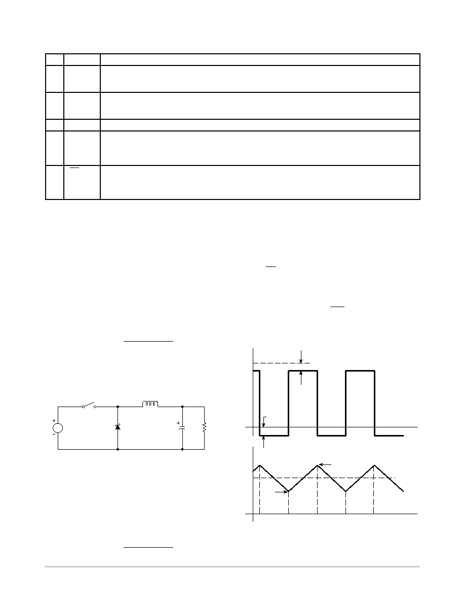
The LM2576 is a “Buck” or StepDown Converter which
is the most elementary forwardmode converter. Its basic
schematic can be seen in Figure 16.
The operation of this regulator topology has two distinct
time periods. The first one occurs when the series switch is
on, the input voltage is connected to the input of the inductor.
The output of the inductor is the output voltage, and the
rectifier (or catch diode) is reverse biased. During this
period, since there is a constant voltage source connected
across the inductor, the inductor current begins to linearly
ramp upwards, as described by the following equation:
I
L(on) +
V
in
–Vout ton
L
During this “on” period, energy is stored within the core
material in the form of magnetic flux. If the inductor is
properly designed, there is sufficient energy stored to carry
the requirements of the load during the “off” period.
Figure 16. Basic Buck Converter
D
Vin
RLoad
L
Cout
Power
Switch
The next period is the “off” period of the power switch.
When the power switch turns off, the voltage across the
inductor reverses its polarity and is clamped at one diode
voltage drop below ground by the catch diode. The current
now flows through the catch diode thus maintaining the load
current loop. This removes the stored energy from the
inductor. The inductor current during this time is:
I
L(off) +
Vout –VD toff
L
This period ends when the power switch is once again
turned on. Regulation of the converter is accomplished by
varying the duty cycle of the power switch. It is possible to
describe the duty cycle as follows:
d
+
ton
T
, where T is the period of switching.
For the buck converter with ideal components, the duty
cycle can also be described as:
d
+
Vout
V
in
Figure 17 shows the buck converter, idealized waveforms
of the catch diode voltage and the inductor current.
Power
Switch
Figure 17. Buck Converter Idealized Waveforms
Power
Switch
Off
Power
Switch
Off
Power
Switch
On
Power
Switch
On
Von(SW)
VD(FWD)
Time
ILoad(AV)
Imin
Ipk
Diode
Power
Switch
Diode
V
oltage
Inductor
Current
相关PDF资料 |
PDF描述 |
|---|---|
| LM2576TV-12G | 7.5 A SWITCHING REGULATOR, 63 kHz SWITCHING FREQ-MAX, PZFM5 |
| LM2596-12MWC | 7.5 A SWITCHING REGULATOR, 173 kHz SWITCHING FREQ-MAX, UUC |
| LM2596-ADJMWC | 7.5 A SWITCHING REGULATOR, 173 kHz SWITCHING FREQ-MAX, UUC |
| LM2596-ADJMDC | 7.5 A SWITCHING REGULATOR, 173 kHz SWITCHING FREQ-MAX, UUC |
| LM2601MDC | 1-CHANNEL POWER SUPPLY SUPPORT CKT, UUC |
相关代理商/技术参数 |
参数描述 |
|---|---|
| LM2576D2TR4-3.3 | 功能描述:直流/直流开关调节器 3.3V 3A Buck PWM RoHS:否 制造商:International Rectifier 最大输入电压:21 V 开关频率:1.5 MHz 输出电压:0.5 V to 0.86 V 输出电流:4 A 输出端数量: 最大工作温度: 安装风格:SMD/SMT 封装 / 箱体:PQFN 4 x 5 |
| LM2576D2TR4-3.3G | 功能描述:直流/直流开关调节器 3.3V 3A Buck PWM RoHS:否 制造商:International Rectifier 最大输入电压:21 V 开关频率:1.5 MHz 输出电压:0.5 V to 0.86 V 输出电流:4 A 输出端数量: 最大工作温度: 安装风格:SMD/SMT 封装 / 箱体:PQFN 4 x 5 |
| LM2576D2TR4-3.3G-CUT TAPE | 制造商:ON 功能描述:LM2576 Series 40 V 3 A 52 kHz Step-Down Switching Regulator - D2PAK-5 |
| LM2576D2TR4-5G | 功能描述:直流/直流开关调节器 5V 3A Buck PWM RoHS:否 制造商:International Rectifier 最大输入电压:21 V 开关频率:1.5 MHz 输出电压:0.5 V to 0.86 V 输出电流:4 A 输出端数量: 最大工作温度: 安装风格:SMD/SMT 封装 / 箱体:PQFN 4 x 5 |
| LM2576DP-12 | 制造商:HTC 制造商全称:HTC Korea TAEJIN Technology Co. 功能描述:3A, 52kHz, Step-Down Switching Regulator |
发布紧急采购,3分钟左右您将得到回复。