- 您现在的位置:买卖IC网 > PDF目录30746 > LM2597-3.3MWA (NATIONAL SEMICONDUCTOR CORP) 1.4 A SWITCHING REGULATOR, 173 kHz SWITCHING FREQ-MAX, UUC PDF资料下载
参数资料
| 型号: | LM2597-3.3MWA |
| 厂商: | NATIONAL SEMICONDUCTOR CORP |
| 元件分类: | 稳压器 |
| 英文描述: | 1.4 A SWITCHING REGULATOR, 173 kHz SWITCHING FREQ-MAX, UUC |
| 封装: | WAFER |
| 文件页数: | 20/40页 |
| 文件大小: | 1019K |
| 代理商: | LM2597-3.3MWA |
第1页第2页第3页第4页第5页第6页第7页第8页第9页第10页第11页第12页第13页第14页第15页第16页第17页第18页第19页当前第20页第21页第22页第23页第24页第25页第26页第27页第28页第29页第30页第31页第32页第33页第34页第35页第36页第37页第38页第39页第40页
Application Information (Continued)
THERMAL CONSIDERATIONS
The LM2597/LM2597HV is available in two packages, an
8-pin through hole DIP (N) and an 8-pin surface mount SO-8
(M). Both packages are molded plastic with a copper lead
frame. When the package is soldered to the PC board, the
copper and the board are the heat sink for the LM2597 and
the other heat producing components.
For best thermal performance, wide copper traces should be
used. Pins should be soldered to generous amounts of
printed circuit board copper, (one exception to this is the
output (switch) pin, which should not have large areas of
copper). Large areas of copper provide the best transfer of
heat (lower thermal resistance) to the surrounding air, and
even double-sided or multilayer boards provide a better heat
path to the surrounding air. Unless power levels are small,
sockets are not recommended because of the added ther-
mal resistance it adds and the resultant higher junction
temperatures.
Package thermal resistance and junction temperature rise
numbers are all approximate, and there are many factors
that will affect the junction temperature. Some of these fac-
tors include board size, shape, thickness, position, location,
and even board temperature. Other factors are, trace width,
printed circuit copper area, copper thickness, single- or
double-sided, multilayer board, and the amount of solder on
the board. The effectiveness of the PC board to dissipate
heat also depends on the size, quantity and spacing of other
components on the board. Furthermore, some of these com-
ponents such as the catch diode will add heat to the PC
board and the heat can vary as the input voltage changes.
For the inductor, depending on the physical size, type of core
material and the DC resistance, it could either act as a heat
sink taking heat away from the board, or it could add heat to
the board.
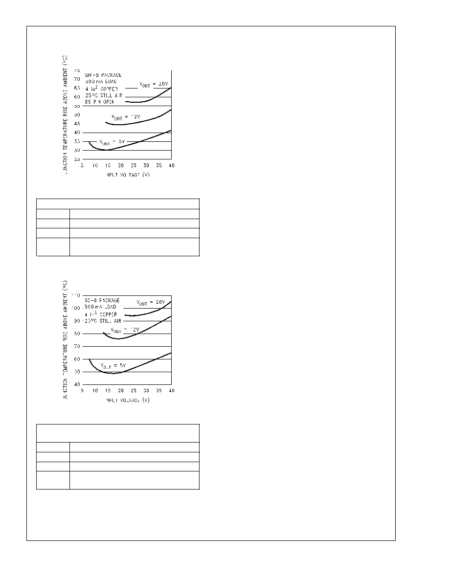
The curves shown in
Figure 22 and Figure 23 show the
LM2597 junction temperature rise above ambient tempera-
ture with a 500 mA load for various input and output volt-
ages. The Bias Supply pin was not used (left open) for these
curves. Connecting the Bias Supply pin to the output voltage
would reduce the junction temperature by approximately 5C
to 15C, depending on the input and output voltages, and the
load current. This data was taken with the circuit operating
as a buck switcher with all components mounted on a PC
board to simulate the junction temperature under actual
operating conditions. This curve is typical, and can be used
for a quick check on the maximum junction temperature for
various conditions, but keep in mind that there are many
factors that can affect the junction temperature.
BIAS SUPPLY FEATURE
The bias supply (V
BS) pin allows the LM2597’s internal
circuitry to be powered from a power source, other than V
IN,
typically the output voltage. This feature can increase effi-
ciency and lower junction temperatures under some operat-
ing conditions. The greatest increase in efficiency occur with
light load currents, high input voltage and low output voltage
(4V to 12V). See efficiency curves shown in
Figure 24 and
Figure 25. The curves with solid lines are with the V
BS pin
connected to the regulated output voltage, while the curves
with dashed lines are with the V
BS pin open.
The bias supply pin requires a minimum of approximately
3.5V at room temperature (4V @ 40C), and can be as high
as 30V, but there is little advantage of using the bias supply
feature with voltages greater than 15V or 20V. The current
required for the V
IN pin is typically 4 mA.
DS012440-41
Circuit Data for Temperature Rise Curve (DIP-8)
Capacitors Through hole electrolytic
Inductor
Through hole, Schott, 100 H
Diode
Through hole, 1A 40V, Schottky
PC board
4 square inches single sided 2 oz. copper
(0.0028")
FIGURE 22. Junction Temperature Rise, DIP-8
DS012440-42
Circuit Data for Temperature Rise Curve (Surface
Mount)
Capacitors Surface mount tantalum, molded “D” size
Inductor
Surface mount, Coilcraft DO33, 100 H
Diode
Surface mount, 1A 40V, Schottky
PC board
4 square inches single sided 2 oz. copper
(0.0028")
FIGURE 23. Junction Temperature Rise, SO-8
LM2597/LM2597HV
www.national.com
27
相关PDF资料 |
PDF描述 |
|---|---|
| LM2597HV-5MWC | 1.4 A SWITCHING REGULATOR, 173 kHz SWITCHING FREQ-MAX, UUC |
| LM2597-5.0MDA | 1.4 A SWITCHING REGULATOR, 173 kHz SWITCHING FREQ-MAX, UUC |
| LM2597-5.0MWA | 1.4 A SWITCHING REGULATOR, 173 kHz SWITCHING FREQ-MAX, UUC |
| LM2645MTDX/NOPB | SWITCHING CONTROLLER, 335 kHz SWITCHING FREQ-MAX, PDSO48 |
| LM2673LDX-12 | 5.4 A SWITCHING REGULATOR, 280 kHz SWITCHING FREQ-MAX, PDSO14 |
相关代理商/技术参数 |
参数描述 |
|---|---|
| LM2597HVM-12 | 功能描述:直流/直流开关转换器 RoHS:否 制造商:STMicroelectronics 最大输入电压:4.5 V 开关频率:1.5 MHz 输出电压:4.6 V 输出电流:250 mA 输出端数量:2 最大工作温度:+ 85 C 安装风格:SMD/SMT |
| LM2597HVM-12/NOPB | 功能描述:直流/直流开关转换器 RoHS:否 制造商:STMicroelectronics 最大输入电压:4.5 V 开关频率:1.5 MHz 输出电压:4.6 V 输出电流:250 mA 输出端数量:2 最大工作温度:+ 85 C 安装风格:SMD/SMT |
| LM2597HVM-12/NOPB | 制造商:Texas Instruments 功能描述:DC/DC Converter IC |
| LM2597HVM-3.3 | 功能描述:直流/直流开关转换器 RoHS:否 制造商:STMicroelectronics 最大输入电压:4.5 V 开关频率:1.5 MHz 输出电压:4.6 V 输出电流:250 mA 输出端数量:2 最大工作温度:+ 85 C 安装风格:SMD/SMT |
| LM2597HVM-3.3/NOPB | 功能描述:直流/直流开关转换器 RoHS:否 制造商:STMicroelectronics 最大输入电压:4.5 V 开关频率:1.5 MHz 输出电压:4.6 V 输出电流:250 mA 输出端数量:2 最大工作温度:+ 85 C 安装风格:SMD/SMT |
发布紧急采购,3分钟左右您将得到回复。