- 您现在的位置:买卖IC网 > PDF目录30746 > LM2597-3.3MWA (NATIONAL SEMICONDUCTOR CORP) 1.4 A SWITCHING REGULATOR, 173 kHz SWITCHING FREQ-MAX, UUC PDF资料下载
参数资料
| 型号: | LM2597-3.3MWA |
| 厂商: | NATIONAL SEMICONDUCTOR CORP |
| 元件分类: | 稳压器 |
| 英文描述: | 1.4 A SWITCHING REGULATOR, 173 kHz SWITCHING FREQ-MAX, UUC |
| 封装: | WAFER |
| 文件页数: | 4/40页 |
| 文件大小: | 1019K |
| 代理商: | LM2597-3.3MWA |
第1页第2页第3页当前第4页第5页第6页第7页第8页第9页第10页第11页第12页第13页第14页第15页第16页第17页第18页第19页第20页第21页第22页第23页第24页第25页第26页第27页第28页第29页第30页第31页第32页第33页第34页第35页第36页第37页第38页第39页第40页
LM2597/LM2597HV Series Buck Regulator Design Procedure (Adjustable
Output)
PROCEDURE (Adjustable Output Voltage Version)
EXAMPLE (Adjustable Output Voltage Version)
Given:
V
OUT = Regulated Output Voltage
V
IN(max) = Maximum Input Voltage
I
LOAD(max) = Maximum Load Current
F = Switching Frequency
(Fixed at a nominal 150 kHz).
Given:
V
OUT = 20V
V
IN(max) = 28V
I
LOAD(max) = 0.5A
F = Switching Frequency
(Fixed at a nominal 150 kHz).
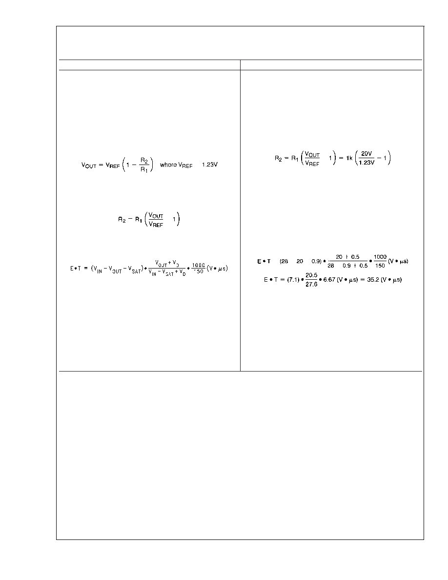
1. Programming Output Voltage (Selecting R
1 and R2,as
shown in
Figure 12)
Use the following formula to select the appropriate resistor
values.
Select a value for R
1 between 240 and 1.5 k. The lower
resistor values minimize noise pickup in the sensitive feed-
back pin. (For the lowest temperature coefficient and the best
stability with time, use 1% metal film resistors.)
1. Programming Output Voltage (Selecting R
1 and R2,as
shown in
Figure 12)
Select R
1 to be 1 k, 1%. Solve for R2.
R
2 = 1k (16.26 1) = 15.26k, closest 1% value is 15.4 k.
R
2 = 15.4 k.
2. Inductor Selection (L1)
A. Calculate the inductor Volt microsecond constant E
T
(V
s), from the following formula:
where V
SAT = internal switch saturation voltage = 0.9V
and V
D = diode forward voltage drop = 0.5V
B. Use the E
T value from the previous formula and match
it with the E
T number on the vertical axis of the Inductor
Value Selection Guide shown in
Figure 6.
C. on the horizontal axis, select the maximum load current.
D. Identify the inductance region intersected by the E
T
value and the Maximum Load Current value. Each region is
identified by an inductance value and an inductor code (LXX).
E. Select an appropriate inductor from the four manufacturer’s
part numbers listed in
Figure 7.
2. Inductor Selection (L1)
A. Calculate the inductor Volt
microsecond constant (E T),
B. E
T = 35.2 (V s)
C. I
LOAD(max) = 0.5A
D. From the inductor value selection guide shown in
Figure 6,
the inductance region intersected by the 35 (V
s) horizontal
line and the 0.5A vertical line is 150 H, and the inductor code
is L19.
E. From the table in
Figure 7, locate line L19, and select an
inductor part number from the list of manufacturers part num-
bers.
LM2597/LM2597HV
www.national.com
12
相关PDF资料 |
PDF描述 |
|---|---|
| LM2597HV-5MWC | 1.4 A SWITCHING REGULATOR, 173 kHz SWITCHING FREQ-MAX, UUC |
| LM2597-5.0MDA | 1.4 A SWITCHING REGULATOR, 173 kHz SWITCHING FREQ-MAX, UUC |
| LM2597-5.0MWA | 1.4 A SWITCHING REGULATOR, 173 kHz SWITCHING FREQ-MAX, UUC |
| LM2645MTDX/NOPB | SWITCHING CONTROLLER, 335 kHz SWITCHING FREQ-MAX, PDSO48 |
| LM2673LDX-12 | 5.4 A SWITCHING REGULATOR, 280 kHz SWITCHING FREQ-MAX, PDSO14 |
相关代理商/技术参数 |
参数描述 |
|---|---|
| LM2597HVM-12 | 功能描述:直流/直流开关转换器 RoHS:否 制造商:STMicroelectronics 最大输入电压:4.5 V 开关频率:1.5 MHz 输出电压:4.6 V 输出电流:250 mA 输出端数量:2 最大工作温度:+ 85 C 安装风格:SMD/SMT |
| LM2597HVM-12/NOPB | 功能描述:直流/直流开关转换器 RoHS:否 制造商:STMicroelectronics 最大输入电压:4.5 V 开关频率:1.5 MHz 输出电压:4.6 V 输出电流:250 mA 输出端数量:2 最大工作温度:+ 85 C 安装风格:SMD/SMT |
| LM2597HVM-12/NOPB | 制造商:Texas Instruments 功能描述:DC/DC Converter IC |
| LM2597HVM-3.3 | 功能描述:直流/直流开关转换器 RoHS:否 制造商:STMicroelectronics 最大输入电压:4.5 V 开关频率:1.5 MHz 输出电压:4.6 V 输出电流:250 mA 输出端数量:2 最大工作温度:+ 85 C 安装风格:SMD/SMT |
| LM2597HVM-3.3/NOPB | 功能描述:直流/直流开关转换器 RoHS:否 制造商:STMicroelectronics 最大输入电压:4.5 V 开关频率:1.5 MHz 输出电压:4.6 V 输出电流:250 mA 输出端数量:2 最大工作温度:+ 85 C 安装风格:SMD/SMT |
发布紧急采购,3分钟左右您将得到回复。