- 您现在的位置:买卖IC网 > PDF目录44549 > LM2636MTCX/NOPB (NATIONAL SEMICONDUCTOR CORP) SWITCHING CONTROLLER, 2000 kHz SWITCHING FREQ-MAX, PDSO20 PDF资料下载
参数资料
| 型号: | LM2636MTCX/NOPB |
| 厂商: | NATIONAL SEMICONDUCTOR CORP |
| 元件分类: | 稳压器 |
| 英文描述: | SWITCHING CONTROLLER, 2000 kHz SWITCHING FREQ-MAX, PDSO20 |
| 封装: | PLASTIC, TSSOP-20 |
| 文件页数: | 2/17页 |
| 文件大小: | 372K |
| 代理商: | LM2636MTCX/NOPB |
Applications Information (Continued)
result in a smaller C
1,C2 and a larger R1. However, too large
an R
1 can also bring error due to the bias current required by
the inverting input pin of the error amplifier. Calculations
show that the following combination is a good one: R
2 =51,
C
1 = 0.022 F, R1 = 5.6 k,C2 = 820 pF.
For a different application or different type of output capaci-
tors, a different compensation scheme may be necessary.
The user can either follow the steps above to figure the ap-
propriate component values or contact the factory for help.
MOSFET SELECTION
The selection of MOSFET switches affects both the effi-
ciency of the whole converter and the current limit setting.
From an efficiency point of view it is suggested that for the
high-side switch, only logic level MOSFETs be used. Stan-
dard MOSFETs can be used for the low side switch when
12V is used to power the BOOTV pin. The lower loss asso-
ciated with the MOSFETs is two-fold — Ohmic loss and
switching loss. The Ohmic loss is easy to calculate whereas
the switching loss is much more difficult to estimate. In gen-
eral the switching loss is directly proportional to the switching
frequency. As the power MOSFET technology advances,
lower and lower gate charge devices will be available. That
should allow the user to go to higher switching frequencies
without the penalty of losing too much efficiency.
As an example, let us select the MOSFETs for a converter
with a target efficiency of 80% at a load of 2.8V, 14A. As-
sume the inductors lose 1W, the capacitors lose 0.75W and
the total switching loss at 300 kHz is 3.2W. The total allowed
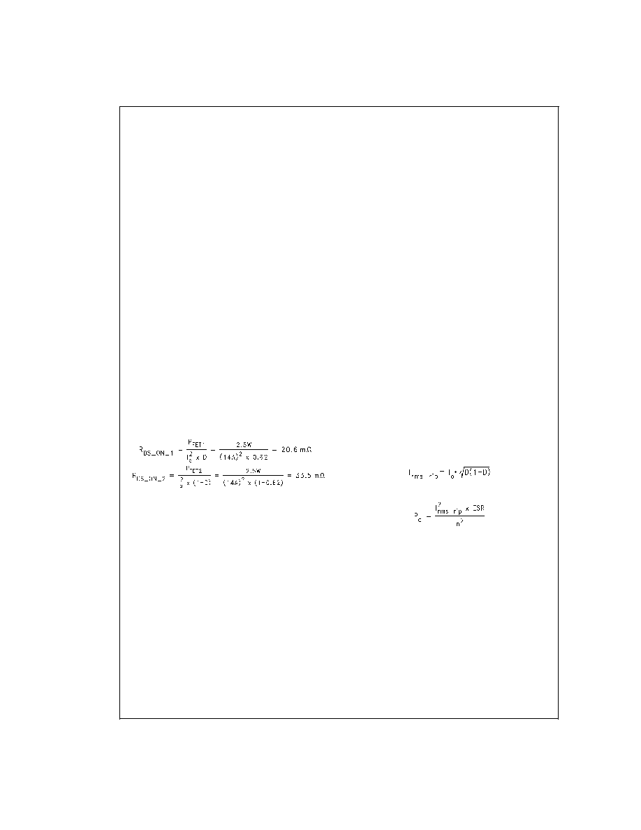
power loss is 9.8W, so the MOSFET Ohmic loss should not
exceed 4.9W. Assume the two switches have the same con-
duction loss, i.e., 2.5W each, then the ON resistance for the
two switches is:
The low side switch ON resistance is much higher than the
high side because at 2.8V the duty cycle is higher than 50%
and becomes even larger at full load. For the high side
switch, an IRL3202 (TO-220 package) or IRL3202S (D
2PAK)
should be sufficient. For the low side switch, an IRL3303
(TO-220 package) or IRL3303S (D
2PAK) should be suffi-
cient. Since each FET is dissipating 3.2W/2 + 2.5W = 4.1W,
it is suggested that appropriate heat sinks be used in the
case of TO-220 package or large enough copper area be
connected to the drain in the case of surface mount pack-
age.
CAPACITOR SELECTION
The selection of capacitors is an extremely important step
when designing a converter for a load such as the
Pentium II. Since the typical slew rate of the load current dur-
ing a large load transient is around 20A/s to 30A/s, the
switching converter has to rely on the output capacitors to
take care of the first few microseconds. Under such a current
slew rate, ESR of the output capacitors is more of a concern
than the ESL. Depending on the kind of capacitors being
used, capacitance of the output capacitors may or may not
be an important factor. When the output capacitance is too
low, the converter may have to have a small output inductor
to quickly supply current to the output capacitors when the
load suddenly kicks in and to quickly stop supplying current
when the load is suddenly removed.
Multilayer ceramic (MLC) capacitors can have very low ESR
but also a low capacitance value compared to other kinds of
capacitors. Low ESR aluminum electrolytic capacitors tend
to have large sizes and capacitances. Tantalum electrolytic
capacitors can have a fairly low ESR with a much smaller
size and capacitance than the aluminum capacitors. Certain
OSCON capacitors present ultra low ESR and long life span.
By the time the total ESR of the output capacitor bank
reaches around 9 m
, the capacitance of the aluminum/
tantalum/OSCON capacitors is usually already in the milli-
farad range. For those capacitors, ESR is the only factor to
consider. MLCs can have the same amount of total ESR with
much less capacitance, most probably under 100 F. A very
small inductor, ultra fast control loop and a high switching
frequency become necessary in such a case to deal with the
fast charging/discharging rate of the output capacitor bank.
From a cost savings point of view, aluminum electrolytic ca-
pacitors are the most popular choice for output capacitors.
They have reasonably long life span and they tend to have
huge capacitance to withstand the charging or discharging
process during a load transient for a fairly long period. Sanyo
MV-GX series gives good performance when enough of the
capacitors are paralleled. The 6MV1500GX capacitor has a
typical ESR of 44 m
. Five of these capacitors should be
sufficient in the case of on-board power supply for a Pentium
II motherboard.
The challenge for input capacitors is the ripple current. The
large ripple current drawn by the high side switch tends to
generate quite some heat due to the capacitor ESR. The
ripple current ratings in the capacitor catalogs are usually
specified under the highest allowable temperature. In the
case of desktop applications, those ratings seem too conser-
vative. A good way to ensure enough number of capacitors is
through lab evaluation. The input current RMS ripple value
can be determined by the following equation:
and the power loss in each input capacitor is:
In the case of Pentium II power supply, the maximum output
current is around 14A. Under the worst case when duty cycle
is 50%, the maximum input capacitor RMS ripple current is
half of output current, i.e., 7A. It is found that three Sanyo
16MV820GX capacitors are enough under room tempera-
ture. The typical ESR of those capacitors is 44 m
.Sothe
power loss in each of them is around (7A)
2 x44m
/32 =
0.24W. Note that the power loss in each capacitor is in-
versely proportional to the square of the total number of ca-
pacitors, which means the power loss in each capacitor
quickly drops when the number of capacitors increases.
INDUCTOR SELECTION
The size of the output is determined by a number of param-
eters. Basically the larger the inductor, the smaller the output
ripple voltage, but the slower the converter’s response
speed during a load transient. On the other hand, a smaller
inductor requires higher switching frequency to maintain the
same level of output ripple, and probably results in a more
lossy converter, but has less inertia responding to load tran-
LM2636
www.national.com
10
相关PDF资料 |
PDF描述 |
|---|---|
| LM2637M/NOPB | SWITCHING CONTROLLER, 1000 kHz SWITCHING FREQ-MAX, PDSO24 |
| LM2637MWC | SWITCHING CONTROLLER, 1000 kHz SWITCHING FREQ-MAX, UUC |
| LM2639MX/NOPB | SWITCHING CONTROLLER, 8700 kHz SWITCHING FREQ-MAX, PDSO24 |
| LM2639M/NOPB | SWITCHING CONTROLLER, 8700 kHz SWITCHING FREQ-MAX, PDSO24 |
| LM2639MWC | SWITCHING CONTROLLER, 8700 kHz SWITCHING FREQ-MAX, UUC |
相关代理商/技术参数 |
参数描述 |
|---|---|
| LM2636MX | 制造商:Texas Instruments 功能描述: |
| LM2636MX/NOPB | 功能描述:IC CTRLR PROG REG 5BIT 20-SOIC RoHS:是 类别:集成电路 (IC) >> PMIC - 电源管理 - 专用 系列:- 应用说明:Ultrasound Imaging Systems Application Note 产品培训模块:Lead (SnPb) Finish for COTS Obsolescence Mitigation Program 标准包装:37 系列:- 应用:医疗用超声波成像,声纳 电流 - 电源:- 电源电压:2.37 V ~ 6 V 工作温度:0°C ~ 70°C 安装类型:表面贴装 封装/外壳:56-WFQFN 裸露焊盘 供应商设备封装:56-TQFN-EP(8x8) 包装:管件 |
| LM2637 | 制造商:未知厂家 制造商全称:未知厂家 功能描述: |
| LM2637A E WAF | 制造商:Texas Instruments 功能描述: |
| LM2637M | 制造商:OC White Company 功能描述:LDO Cntrlr REG CTRLR 1.3V to 3.5V 24-Pin SOIC W Rail |
发布紧急采购,3分钟左右您将得到回复。