- 您现在的位置:买卖IC网 > PDF目录32307 > LM4873LQX/NOPB (NATIONAL SEMICONDUCTOR CORP) 3 W, 2 CHANNEL, AUDIO AMPLIFIER, QCC24 PDF资料下载
参数资料
| 型号: | LM4873LQX/NOPB |
| 厂商: | NATIONAL SEMICONDUCTOR CORP |
| 元件分类: | 音频/视频放大 |
| 英文描述: | 3 W, 2 CHANNEL, AUDIO AMPLIFIER, QCC24 |
| 封装: | LLP-24 |
| 文件页数: | 8/25页 |
| 文件大小: | 963K |
| 代理商: | LM4873LQX/NOPB |
Application Information (Continued)
microprocessor, or a microcontroller. When using a switch,
connect an external 10k
pull-up resistor between the
SHUTDOWN pin and V
DD. Connect the switch between the
SHUTDOWN pin and ground. Select normal amplifier opera-
tion by closing the switch. Opening the switch connects the
SHUTDOWN pin to V
DD through the pull-up resistor, activat-
ing micro-power shutdown. The switch and resistor guaran-
tee that the SHUTDOWN pin will not float. This prevents
unwanted state changes. In a system with a microprocessor
or a microcontroller, use a digital output to apply the control
voltage to the SHUTDOWN pin. Driving the SHUTDOWN pin
with active circuitry eliminates the pull up resistor.
TABLE 1. Logic Level Truth Table for SHUTDOWN, HP-IN, and MUX Operation
SHUTDOWN
PIN
HP-INPIN
MUX CHANNEL
SELECT PIN
OPERATIONAL MODE
(MUX INPUT CHANNEL #)
Logic Low
Bridged Amplifiers (1)
Logic Low
Logic High
Bridged Amplifiers (2)
Logic Low
Logic High
Logic Low
Single-Ended Amplifiers (1)
Logic Low
Logic High
Single-Ended Amplifiers (2)
Logic High
X
Micro-Power Shutdown
HP-IN FUNCTION
Applying a voltage between 4V and V
DD to the LM4873’s
HP-IN headphone control pin turns off Amp2A and Amp2B,
muting a bridged-connected load. Quiescent current con-
sumption is reduced when the IC is in this single-ended
mode.
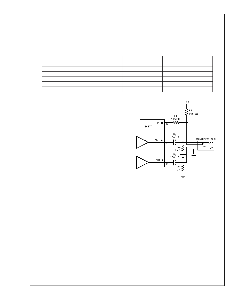
Figure 3 shows the implementation of the LM4873’s head-
phone control function. With no headphones connected to
the headphone jack, the R1-R2 voltage divider sets the
voltage applied to the HP-IN pin (pin 16) at approximately
50mV. This 50mV enables Amp1B and Amp2B, placing the
LM4873 in bridged mode operation. The output coupling
capacitor blocks the amplifier’s half supply DC voltage, pro-
tecting the headphones.
The HP-IN threshold is set at 4V. While the LM4873 operates
in bridged mode, the DC potential across the load is essen-
tially 0V. Therefore, even in an ideal situation, the output
swing cannot cause a false single-ended trigger. Connecting
headphones to the headphone jack disconnects the head-
phone jack contact pin from OUTA and allows R1 to pull the
HP Sense pin up to V
DD. This enables the headphone func-
tion, turns off Amp2A and Amp2B, and mutes the bridged
speaker. The amplifier then drives the headphones, whose
impedance is in parallel with resistor R2 and R3. These
resistors have negligible effect on the LM4873’s output drive
capability since the typical impedance of headphones is
32
.
Figure 3 also shows the suggested headphone jack electri-
cal connections. The jack is designed to mate with a three-
wire plug. The plug’s tip and ring should each carry one of
the two stereo output signals, whereas the sleeve should
carry the ground return. A headphone jack with one control
pin contact is sufficient to drive the HP-IN pin when connect-
ing headphones.
A microprocessor or a switch can replace the headphone
jack contact pin. When a microprocessor or switch applies a
voltage greater than 4V to the HP-IN pin, a bridge-connected
speaker is muted and Amp1A and Amp2A drive a pair of
headphones.
SELECTING PROPER EXTERNAL COMPONENTS
Optimizing the LM4873’s performance requires properly se-
lecting external components. Though the LM4873 operates
well when using external components with wide tolerances,
best performance is achieved by optimizing component val-
ues.
The LM4873 is unity-gain stable, giving a designer maximum
design flexibility. The gain should be set to no more than a
given application requires. This allows the amplifier to
achieve minimum THD+N and maximum signal-to-noise ra-
tio. These parameters are compromised as the closed-loop
gain increases. However, low gain demands input signals
with greater voltage swings to achieve maximum output
power. Fortunately, many signal sources such as audio
CODECs have outputs of 1V
RMS (2.83VP-P). Please refer to
the Audio Power Amplifier Design section for more infor-
mation on selecting the proper gain.
10099324
FIGURE 3. Headphone Circuit
LM4873
www.national.com
16
相关PDF资料 |
PDF描述 |
|---|---|
| LM4891MMX/NOPB | 1 W, 1 CHANNEL, AUDIO AMPLIFIER, PDSO8 |
| LM4891MX/NOPB | 1 W, 1 CHANNEL, AUDIO AMPLIFIER, PDSO8 |
| LM4891LDX/NOPB | 1 W, 1 CHANNEL, AUDIO AMPLIFIER, PDSO10 |
| LM4898MMXNPAU | 1 W, 1 CHANNEL, AUDIO AMPLIFIER, PDSO10 |
| LM4898ITLX/NOPB | 1 W, 1 CHANNEL, AUDIO AMPLIFIER, PBGA9 |
相关代理商/技术参数 |
参数描述 |
|---|---|
| LM4873MT | 制造商:Texas Instruments 功能描述: |
| LM4873MT/NOPB | 功能描述:IC AMP AUDIO PWR 3W STER 20TSSOP RoHS:是 类别:集成电路 (IC) >> 线性 - 音頻放大器 系列:Boomer® 产品培训模块:Lead (SnPb) Finish for COTS Obsolescence Mitigation Program 标准包装:2,500 系列:DirectDrive® 类型:H 类 输出类型:耳机,2-通道(立体声) 在某负载时最大输出功率 x 通道数量:35mW x 2 @ 16 欧姆 电源电压:1.62 V ~ 1.98 V 特点:I²C,麦克风,静音,短路保护,音量控制 安装类型:表面贴装 供应商设备封装:25-WLP(2.09x2.09) 封装/外壳:25-WFBGA,WLCSP 包装:带卷 (TR) |
| LM4873MTE | 制造商:Rochester Electronics LLC 功能描述: 制造商:Texas Instruments 功能描述: |
| LM4873MTE/NOPB | 功能描述:音频放大器 Dual 2.1W Audio Amp Plus Stereo HdPh Fcn RoHS:否 制造商:STMicroelectronics 产品:General Purpose Audio Amplifiers 输出类型:Digital 输出功率: THD + 噪声: 工作电源电压:3.3 V 电源电流: 最大功率耗散: 最大工作温度: 安装风格:SMD/SMT 封装 / 箱体:TQFP-64 封装:Reel |
| LM4873MTE-1 | 功能描述:IC AMP AUDIO PWR 3W STER 28TSSOP RoHS:是 类别:集成电路 (IC) >> 线性 - 音頻放大器 系列:Boomer® 产品培训模块:Lead (SnPb) Finish for COTS Obsolescence Mitigation Program 标准包装:2,500 系列:DirectDrive® 类型:H 类 输出类型:耳机,2-通道(立体声) 在某负载时最大输出功率 x 通道数量:35mW x 2 @ 16 欧姆 电源电压:1.62 V ~ 1.98 V 特点:I²C,麦克风,静音,短路保护,音量控制 安装类型:表面贴装 供应商设备封装:25-WLP(2.09x2.09) 封装/外壳:25-WFBGA,WLCSP 包装:带卷 (TR) |
发布紧急采购,3分钟左右您将得到回复。