- 您现在的位置:买卖IC网 > PDF目录32308 > LSP3171MSAD (LITE-ON SEMICONDUCTOR CORP) SWITCHING REGULATOR, 470 kHz SWITCHING FREQ-MAX, PDSO10 PDF资料下载
参数资料
| 型号: | LSP3171MSAD |
| 厂商: | LITE-ON SEMICONDUCTOR CORP |
| 元件分类: | 稳压器 |
| 英文描述: | SWITCHING REGULATOR, 470 kHz SWITCHING FREQ-MAX, PDSO10 |
| 封装: | MSOP-10 |
| 文件页数: | 5/9页 |
| 文件大小: | 330K |
| 代理商: | LSP3171MSAD |
Liteon Semiconductor Corporation
LSP3171
MSOP10L 2A Step Down DC/DC Converter
Rev1.4
5/9
For ceramic output capacitors, typically choose a capacitance of about 22F. For tantalum or electrolytic capacitors,
choose a capacitor with less than 50m ESR.
Rectifier Diode
Use a Schottky diode as the rectifier to conduct current when the High-Side Power Switch is off. The Schottky diode
must have a current rating higher than the maximum output current and a reverse voltage rating higher than the
maximum input voltage.
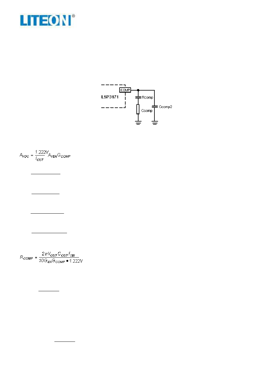
Stability Compensation
CCOMP2 is needed only for high ESR output capacitor
Figure 2. Stability Compensation
The feedback loop of the IC is stabilized by the components at the COMP pin, as shown in Figure 2. The DC loop
gain of the system is determined by the following equation:
(4)
The dominant pole P1 is due to CCOMP:
COMP
VEA
EA
1
P
C
A
π
2
G
f
=
(5)
The second pole P2 is the output pole:
OUT
2
P
C
V
π
2
I
f
=
(6)
The first zero Z1 is due to RCOMP and CCOMP:
COMP
1
Z
C
R
π
2
1
f
=
(7)
And finally, the third pole is due to RCOMP and CCOMP2 (if CCOMP2 is used):
2
COMP
3
P
C
R
π
2
1
f
=
(8)
The following steps should be used to compensate the IC:
STEP1. Set the crossover frequency at 1/10 of the switching frequency via RCOMP:
(9)
but limit RCOMP to 3.4k maximum.
STEP2. Set the zero fZ1 at 1/4 of the crossover frequency. If RCOMP is less than 3.4k, the equation for CCOMP
is:
)
F
(
R
10
8
.
1
C
COMP
5
COMP
×
=
(10)
If RCOMP is limited to 3.4k, then the actual crossover frequency is 3.4 / (VOUTCOUT). Therefore:
)
F
(
C
V
10
2
.
1
C
OUT
5
COMP
×
=
(11)
STEP3. If the output capacitor’s ESR is high enough to cause a zero at lower than 4 times the crossover frequency,
an additional compensation capacitor CCOMP2 is required. The condition for using CCOMP2 is:
ESRCOUT
R
)
(
V
012
.
0
,
C
10
1
.
1
Min
OUT
6
×
≥
(12)
相关PDF资料 |
PDF描述 |
|---|---|
| LT1009CPWG4 | 1-OUTPUT TWO TERM VOLTAGE REFERENCE, 2.5 V, PDSO8 |
| LT1009IPWG4 | 1-OUTPUT TWO TERM VOLTAGE REFERENCE, 2.5 V, PDSO8 |
| LT140SAB | SPECIALTY ANALOG CIRCUIT, PDSO4 |
| LT230A | SPECIALTY ANALOG CIRCUIT, PDSO4 |
| LT3483AEDC#TRMPBF | 0.46 A SWITCHING REGULATOR, PDSO8 |
相关代理商/技术参数 |
参数描述 |
|---|---|
| LSP32-K2-RGBA | 制造商:Dialight 功能描述:LED MODULE 32X K2 RGBA |
| LSP-32K2-RGBW | 制造商:Dialight 功能描述: |
| LSP32-K2-RGBW | 制造商:Dialight 功能描述:LED MODULE 32X K2 RGBW |
| LSP-32K2-WWWW | 制造商:Dialight 功能描述: |
| LSP32-K2-WWWW | 制造商:Dialight 功能描述:LED MODULE 32X K2 WWWW |
发布紧急采购,3分钟左右您将得到回复。