- 您现在的位置:买卖IC网 > PDF目录79907 > LT1240-7DZFB1 (POWER-ONE INC) 1-OUTPUT 500 W AC-DC REG PWR SUPPLY MODULE PDF资料下载
参数资料
| 型号: | LT1240-7DZFB1 |
| 厂商: | POWER-ONE INC |
| 元件分类: | 电源模块 |
| 英文描述: | 1-OUTPUT 500 W AC-DC REG PWR SUPPLY MODULE |
| 封装: | CASE T01, MODULE |
| 文件页数: | 24/33页 |
| 文件大小: | 864K |
| 代理商: | LT1240-7DZFB1 |
第1页第2页第3页第4页第5页第6页第7页第8页第9页第10页第11页第12页第13页第14页第15页第16页第17页第18页第19页第20页第21页第22页第23页当前第24页第25页第26页第27页第28页第29页第30页第31页第32页第33页
Cassette Style
AC-DC Converters
T Series
Edition 5/5.2000
30/33
Table 21: H15 Connector pin allocation
Pin
Electrical determination
Designation
4
Phase
P~
6
Neutral
N~
8
Protective earth 1
10
Protective earth 1
12
Output voltage positive
Vo+
14
Output voltage positive
Vo+
16
Hot plug-in contact 1 3 positive
HC+
18
Hot plug-in contact 1 3 negative
HC–
20
Output voltage negative
Vo-
22
Output voltage negative
Vo-
24
System good signal input
Sys In
26
System good signal output
Sys Out
28
Inhibit input 2 or Remote control input
i/
Ucr
30
Power down signal
D
32
Power down signal threshold of
Uo
D set
1 Leading pin (pre-connecting).
2 Unit operates with open inhibit.
3 External connections see: Auxiliary Functions: Power Boosting,
Redundant Configuration, Hot Plug-in.
Safety and Installation Instructions
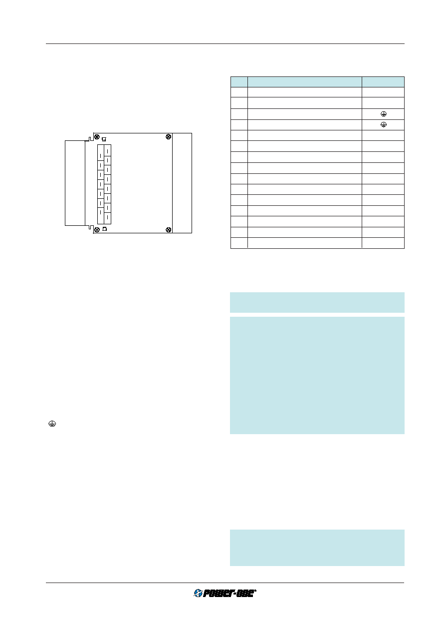
Connector Pin Allocation
The connector pin allocation table defines the electrical
potentials and the physical pin positions on the H15 con-
nector. Pin no. 8 and pin no. 10, the protective earth pins
present on all T series AC-DC converters are leading, en-
suring that they make contact with the female connector
first.
Fig. 54
View of module’s male H15 connector
Installation Instruction
The T series AC-DC converters are components, intended
exclusively for inclusion within other equipment by an in-
dustrial assembly operation or by professional installers. In-
stallation must strictly follow the national safety regulations
in compliance with the enclosure, mounting, creepage,
clearance, casualty, markings and segregation require-
ments of the end-use application. See also:
Technical Infor-
mation: Installation and Application.
Connection to the system shall be made via the female con-
nector H15 (see:
Accessories) according to: Connector pin
allocation. Other installation methods may not meet the
safety requirements.
Check for hazardous voltages before altering any connec-
tions.
The AC-DC converters are provided with pins 8 and 10
(
), which are reliably connected to the case. For safety
reasons it is essential to connect at least one of these pins
to the protective earth of the supply system.
The P~ input (pin no. 4) is internally fused. This fuse is de-
signed to protect the unit in case of overcurrent and may
not be able to satisfy all customer requirements. External
fuses in the wiring to one or both input pins (no. 4 and/or no.
6) may therefore be necessary to ensure compliance with
local requirements. A second fuse in the wiring to the neu-
tral terminal N~ is needed if:
Local requirements demand an individual fuse in each
source line
Neutral to earth impedance is high or undefined
Phase and neutral of the mains are not defined or cannot
be assigned to the corresponding terminals (L to phase
and N to neutral).
Important: Do not open the modules, or guarantee will
be invalidated.
Caution: Prior to handling, the AC-DC converter must
be disconnected from mains and from other sources
(e.g. batteries). Check for hazardous voltages and haz-
ardous energy before and after altering any connec-
tions. Hazardous energy levels may be present at the
output terminals for 3 minutes even after the mains input
voltage has been disconnected from the unit. This is in-
dicated by the red error LED. It is the responsibility of the
installer to prevent an unwanted short-circuit of the AC-
DC converter and of the batteries. To prevent an un-
wanted short-circuit across the output of a disconnected
unit, pins 16 and 18 are leading. In case of a short-circuit
across the output of a T-unit, all LEDs will be off, though
the mains may be present.
Due to high output current value, the T series AC-DC con-
verters provide for each the positive and the negative out-
put path two internally parallel connected contacts (pins 12/
14 and pins 20/22 respectively). It is recommended to con-
nect the load to both female connector pins of each path in
order to keep the voltage drop and power loss across the
connector pins to an absolute minimum.
If a T series AC-DC converter is used for battery charging,
check wether the position of the cell voltage selector switch
corresponds to the required battery cell voltage prior to
putting a system into operation.
Caution: Lead-acid batteries can generate H2 and O2
gas which can form explosive mixtures. Sufficient venti-
lation must be provided in battery cabinets and installa-
tion rooms.
4
6
8
12
10
14
16
18
20
22
24
26
28
30
32
10079
相关PDF资料 |
PDF描述 |
|---|---|
| LKP5660-6D6 | 2-OUTPUT 250 W AC-DC PWR FACTOR CORR MODULE |
| LKP5660-6ED5 | 2-OUTPUT 250 W AC-DC PWR FACTOR CORR MODULE |
| LKP5660-6ERD5T | 2-OUTPUT 250 W AC-DC PWR FACTOR CORR MODULE |
| LKP5660-6PD9T | 2-OUTPUT 250 W AC-DC PWR FACTOR CORR MODULE |
| LKP5661-5D2B1 | 2-OUTPUT 250 W AC-DC PWR FACTOR CORR MODULE |
相关代理商/技术参数 |
参数描述 |
|---|---|
| LT1240-7Z | 制造商:POWER-ONE 制造商全称:Power-One 功能描述:500 Watt AC-DC Converters |
| LT1241 | 制造商:LINER 制造商全称:Linear Technology 功能描述:High Speed Current Mode Pulse Width Modulators |
| LT1241CJ8 | 制造商:未知厂家 制造商全称:未知厂家 功能描述:Current-Mode SMPS Controller |
| LT1241CN8 | 功能描述:IC REG CTRLR ISO PWM CM 8-DIP RoHS:否 类别:集成电路 (IC) >> PMIC - 稳压器 - DC DC 切换控制器 系列:- 标准包装:2,500 系列:- PWM 型:电流模式 输出数:1 频率 - 最大:500kHz 占空比:96% 电源电压:4 V ~ 36 V 降压:无 升压:是 回扫:无 反相:无 倍增器:无 除法器:无 Cuk:无 隔离:无 工作温度:-40°C ~ 125°C 封装/外壳:24-WQFN 裸露焊盘 包装:带卷 (TR) |
| LT1241CN8#PBF | 功能描述:IC REG CTRLR ISO PWM CM 8-DIP RoHS:是 类别:集成电路 (IC) >> PMIC - 稳压器 - DC DC 切换控制器 系列:- 标准包装:2,500 系列:- PWM 型:电流模式 输出数:1 频率 - 最大:500kHz 占空比:96% 电源电压:4 V ~ 36 V 降压:无 升压:是 回扫:无 反相:无 倍增器:无 除法器:无 Cuk:无 隔离:无 工作温度:-40°C ~ 125°C 封装/外壳:24-WQFN 裸露焊盘 包装:带卷 (TR) |
发布紧急采购,3分钟左右您将得到回复。