- 您现在的位置:买卖IC网 > PDF目录22239 > LT1249CS8#TRPBF (Linear Technology)IC PFC CTRLR AVERAGE CURR 8SOIC PDF资料下载
参数资料
| 型号: | LT1249CS8#TRPBF |
| 厂商: | Linear Technology |
| 文件页数: | 8/12页 |
| 文件大小: | 197K |
| 描述: | IC PFC CTRLR AVERAGE CURR 8SOIC |
| 标准包装: | 2,500 |
| 模式: | 平均电流 |
| 频率 - 开关: | 100kHz |
| 电流 - 启动: | 250µA |
| 电源电压: | 15.5 V ~ 27 V |
| 工作温度: | 0°C ~ 100°C |
| 安装类型: | 表面贴装 |
| 封装/外壳: | 8-SOIC(0.154",3.90mm 宽) |
| 供应商设备封装: | 8-SOIC |
| 包装: | 带卷 (TR) |
8
LT1249
The Figure 3 circuit therefore has 382V on V
OUT
, and an
overvoltage level = (V
OUT
+ 44V), or 426V. With a 22礎
hysteresis, V
OUT
then has to drop 22V to 404V before
feedback recovers and the switch turns back on.
M
OUT
is a high impedance current output. In the current
loop, offset line current is determined by multiplier offset
current and input offset voltage of the current amplifier.
A negative 4mV current amplifier V
OS
translates into
20mA line current and 5W input power for 250V line if
0.2& sense resistor is used. Under no load or when the
load power is less than this offset input power, V
OUT
would
slowly charge up to an overvoltage state because the
overvoltage comparator can only reduce multiplier output
current to zero. This does not guarantee zero output
current if the current amplifier has offset. To regulate V
OUT
under this condition, the amplifier M1 (see Block Dia-
gram), becomes active in the current loop when VA
OUT
goes down to 1V. The M1 can put out up to 15礎 to the 4k
resistor at the inverting input to cancel the current ampli-
fier negative V
OS
and keep V
OUT
error to within 2V.
Undervoltage Lockout
The LT1249 turns on when V
CC
is higher than 16V and
remains on until V
CC
falls below 10V, whereupon the chip
enters the lockout state. In the lockout state, the LT1249
only draws 250礎, the oscillator is off, the V
REF
and the
GTDR pins remain low to keep the power MOSFET off.
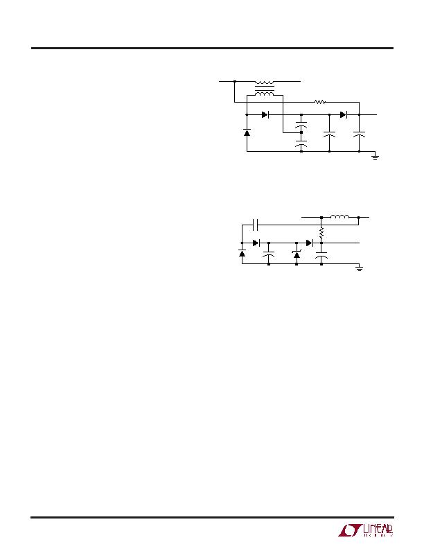
Start-Up and Supply Voltage
The LT1249 draws only 250礎 before the chip starts at
16V on V
CC
. To trickle start, a 90k resistor from the power
line to V
CC
supplies the trickle current and C4 holds the V
CC
up while switching starts (see Figure 4). Then the auxiliary
winding takes over and supplies the operating current.
Note that D3 and the large value C3, in both Figures 4 and
5, are only necessary for systems that have sudden large
load variation down to minimum load and/or very light
load conditions. Under these conditions, the loop may
exhibit a start/restart mode because switching remains off
long enough for C4 to discharge below 10V. The C3 will
hold V
CC
up until switching resumes. For less severe load
variations, D3 is replaced with a short and C3 is omitted.
The turns ratio between the primary winding and the
APPLICATIONS INFORMATION
U
U
U
V
CC
R1
90k
1W
18V
1249 F05
+
C3
390礔
35V
C4
56礔
35V
+
LINE
MAIN INDUCTOR
C2
1000pF
450V
D3
D1
D2
Figure 5. Power Supply for LT1249
auxiliary winding determines V
CC
according to: V
OUT
/(V
CC
2V) = N
P
/N
S
. For 382V V
OUT
and 18V V
CC
, N
P
/N
S
H 19.
In Figure 5 a new technique for supply voltage eliminates
the need for an extra inductor winding. It uses capacitor
charge transfer to generate a constant current source
which feeds a Zener diode. Current to the Zener is equal to
(V
OUT
V
Z
)(C)(f), where V
Z
is Zener voltage and f is
switching frequency. For V
OUT
= 382V, V
Z
= 18V, C =
1000pF and f = 100kHz, Zener current will be 36mA. This
is enough to operate the LT1249, including the FET gate
drive.
Output Capacitor
The peak-to-peak 120Hz output ripple is determined by:
V
P-P
= (2)(I
LOAD
DC)(Z)
where I
LOAD
DC: DC load current
Z: capacitor impedance at 120Hz
For 180礔 at 300W load, I
LOAD
DC = 300W/385V = 0.78A,
V
CC
N
P
N
S
R1
90k
1W
C1
2礔
1249 F04
+
+
C2
2礔
C3
390礔
+
C4
56礔
+
LINE
ALL CAPACITORS ARE RATED 35V
MAIN INDUCTOR
D2
D3
D1
Figure 4. Power Supply for LT1249
相关PDF资料 |
PDF描述 |
|---|---|
| RBB108DHLN | CONN EDGECARD 216PS DIP .050 SLD |
| T95R107M025ESZS | CAP TANT 100UF 25V 20% 2824 |
| SS10P4-M3/86A | DIODE SCHOTTKY 10A 40V SMPC |
| 395-130-542-804 | CARD EDGE 130PS DL .100X.200 BLK |
| LT1249CS8#TR | IC PFC CTRLR AVERAGE CURR 8SOIC |
相关代理商/技术参数 |
参数描述 |
|---|---|
| LT1249I | 制造商:LINER 制造商全称:Linear Technology 功能描述:Power Factor Controller |
| LT1249IN8 | 功能描述:IC PFC CTRLR AVERAGE CURR 8DIP RoHS:否 类别:集成电路 (IC) >> PMIC - PFC(功率因数修正) 系列:- 产品培训模块:GreenChip Synchronous Rectification Control Family of ICs 标准包装:1 系列:- 模式:间歇导电(DCM) 频率 - 开关:- 电流 - 启动:- 电源电压:8.6 V ~ 38 V 工作温度:-20°C ~ 150°C 安装类型:表面贴装 封装/外壳:14-SOIC(0.154",3.90mm 宽) 供应商设备封装:14-SO 包装:Digi-Reel® 其它名称:568-5348-6 |
| LT1249IN8#PBF | 功能描述:IC PFC CTRLR AVERAGE CURR 8DIP RoHS:是 类别:集成电路 (IC) >> PMIC - PFC(功率因数修正) 系列:- 产品培训模块:GreenChip Synchronous Rectification Control Family of ICs 标准包装:1 系列:- 模式:间歇导电(DCM) 频率 - 开关:- 电流 - 启动:- 电源电压:8.6 V ~ 38 V 工作温度:-20°C ~ 150°C 安装类型:表面贴装 封装/外壳:14-SOIC(0.154",3.90mm 宽) 供应商设备封装:14-SO 包装:Digi-Reel® 其它名称:568-5348-6 |
| LT1249IS8 | 功能描述:IC PFC CTRLR AVERAGE CURR 8SOIC RoHS:否 类别:集成电路 (IC) >> PMIC - PFC(功率因数修正) 系列:- 产品培训模块:GreenChip Synchronous Rectification Control Family of ICs 标准包装:1 系列:- 模式:间歇导电(DCM) 频率 - 开关:- 电流 - 启动:- 电源电压:8.6 V ~ 38 V 工作温度:-20°C ~ 150°C 安装类型:表面贴装 封装/外壳:14-SOIC(0.154",3.90mm 宽) 供应商设备封装:14-SO 包装:Digi-Reel® 其它名称:568-5348-6 |
| LT1249IS8#PBF | 功能描述:IC PFC CTRLR AVERAGE CURR 8SOIC RoHS:是 类别:集成电路 (IC) >> PMIC - PFC(功率因数修正) 系列:- 产品培训模块:GreenChip Synchronous Rectification Control Family of ICs 标准包装:1 系列:- 模式:间歇导电(DCM) 频率 - 开关:- 电流 - 启动:- 电源电压:8.6 V ~ 38 V 工作温度:-20°C ~ 150°C 安装类型:表面贴装 封装/外壳:14-SOIC(0.154",3.90mm 宽) 供应商设备封装:14-SO 包装:Digi-Reel® 其它名称:568-5348-6 |
发布紧急采购,3分钟左右您将得到回复。