- 您现在的位置:买卖IC网 > PDF目录14134 > LT1307BCS8#TRPBF (Linear Technology)IC REG BOOST 3.3V/5V 0.1A 8SOIC PDF资料下载
参数资料
| 型号: | LT1307BCS8#TRPBF |
| 厂商: | Linear Technology |
| 文件页数: | 12/20页 |
| 文件大小: | 0K |
| 描述: | IC REG BOOST 3.3V/5V 0.1A 8SOIC |
| 标准包装: | 2,500 |
| 类型: | 升压(升压) |
| 输出类型: | 固定 |
| 输出数: | 1 |
| 输出电压: | 3.3V,5V |
| 输入电压: | 1 V ~ 5 V |
| PWM 型: | 电流模式,混合 |
| 频率 - 开关: | 600kHz |
| 电流 - 输出: | 100mA |
| 同步整流器: | 无 |
| 工作温度: | -40°C ~ 85°C |
| 安装类型: | 表面贴装 |
| 封装/外壳: | 8-SOIC(0.154",3.90mm 宽) |
| 包装: | 带卷 (TR) |
| 供应商设备封装: | 8-SOIC |
�� �
�
�LT1307/LT1307B�
�APPLICATIO� S� I� FOR� ATIO�
�LAYOUT� HINTS�
�The� LT1307� switches� current� at� high� speed,� mandating�
�careful� attention� to� layout� for� proper� performance.� You� will�
�not� get� advertised� performance� with� careless� layouts.�
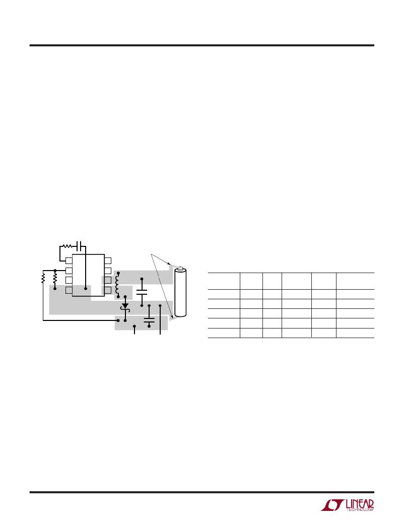
�Figure� 12� shows� recommended� component� placement.�
�Follow� this� closely� in� your� PC� layout.� Note� the� direct� path�
�of� the� switching� loops.� Input� capacitor� C� IN� must� be� placed�
�close� (<� 5mm)� to� the� IC� package.� As� little� as� 10mm� of� wire�
�or� PC� trace� from� C� IN� to� V� IN� will� cause� problems� such� as�
�inability� to� regulate� or� oscillation.� A� 1� μ� F� ceramic� bypass�
�capacitor� is� the� only� input� capacitance� required� provided�
�the� battery� has� a� low� inductance� path� to� the� circuit.� The�
�battery� itself� provides� the� bulk� capacitance� the� device�
�requires� for� proper� operation.� If� the� battery� is� located� some�
�distance� from� the� circuit,� an� additional� input� capacitor� may�
�be� required.� A� 100� μ� F� aluminum� electrolytic� unit� works� well�
�in� these� cases.� This� capacitor� need� not� have� low� ESR.�
�COMPONENT� SELECTION�
�Inductors�
�Inductors� appropriate� for� use� with� the� LT1307� must� pos-�
�sess� three� attributes.� First,� they� must� have� low� core� loss� at�
�600kHz.� Most� ferrite� core� units� have� acceptable� losses� at�
�this� switching� frequency.� Inexpensive� iron� powder� cores�
�should� be� viewed� suspiciously,� as� core� losses� can� cause�
�significant� efficiency� penalties� at� 600kHz.� Second,� the�
�inductor� must� handle� current� of� 500mA� without� saturat-�
�ing.� This� places� a� lower� limit� on� the� physical� size� of� the� unit.�
�Molded� chokes� or� chip� inductors� usually� do� not� have�
�enough� core� to� support� 500mA� current� and� are� unsuitable�
�for� the� application.� Lastly,� the� inductor� should� have� low�
�DCR� (copper� wire� resistance)� to� prevent� efficiency-killing�
�I� 2� R� losses.� Linear� Technology� has� identified� several� induc-�
�tors� suitable� for� use� with� the� LT1307.� This� is� not� an�
�R� C�
�1�
�2�
�C� C�
�LT1307�
�8�
�7�
�KEEP� TRACES�
�OR� LEADS� SHORT!�
�exclusive� list.� There� are� many� magnetics� vendors� whose�
�components� are� suitable� for� use.� A� few� vendor’s� compo-�
�nents� are� listed� in� Table� 1.�
�Table� 1.� Inductors� Suitable� for� Use� with� the� LT1307�
�R1�
�R2�
�3�
�4�
�6�
�5�
�L�
�C� IN�
�PART�
�LQH3C100�
�VALUE�
�10� μ� H�
�MAX�
�DCR�
�0.57�
�MFR�
�Murata-Erie�
�HEIGHT�
�(mm)�
�2.0�
�COMMENT�
�Smallest� Size�
�D�
�DO1608-103�
�10� μ� H�
�0.16�
�Coilcraft�
�3.0�
�C� OUT�
�CD43-100�
�CD54-100�
�10� μ� H�
�10� μ� H�
�0.18�
�0.10�
�Sumida�
�Sumida�
�3.2�
�4.5�
�Best� Efficiency�
�V� OUT�
�GROUND�
�1307� F12�
�CTX32CT-100�
�10� μ� H�
�0.50�
�Coiltronics�
�2.2�
�1210� Footprint�
�Figure� 12.� Recommended� Component� Placement.� Traces�
�Carrying� High� Current� Are� Direct.� Trace� Area� at� FB� Pin� and� V� C�
�Pin� is� Kept� Low.� Lead� Length� to� Battery� Should� Be� Kept� Short�
�OPERATION� FROM� A� LABORATORY� POWER� SUPPLY�
�If� a� lab� supply� is� used,� the� leads� used� to� connect� the� circuit�
�to� the� supply� can� have� significant� inductance� at� the�
�LT1307’s� switching� frequency.� As� in� the� previous� situa-�
�tion,� an� electrolytic� capacitor� may� be� required� at� the� circuit�
�in� order� to� reduce� the� AC� impedance� of� the� input� suffi-�
�ciently.� An� alternative� solution� would� be� to� attach� the�
�circuit� directly� to� the� power� supply� at� the� supply� terminals,�
�without� the� use� of� leads.� The� power� supply’s� output�
�Capacitors�
�For� single� cell� applications,� a� 10� μ� F� ceramic� output� capaci-�
�tor� is� generally� all� that� is� required.� Ripple� voltage� in� Burst�
�Mode� can� be� reduced� by� increasing� output� capacitance.�
�For� 2-� and� 3-cell� applications,� more� than� 10� μ� F� is� needed.�
�For� a� typical� 2-cell� to� 5V� application,� a� 47� μ� F� to� 100� μ� F� low�
�ESR� tantalum� capacitor� works� well.� AVX� TPS� series� (100%�
�surge� tested)� or� Sprague� (don’t� be� vague—ask� for� Sprague)�
�594D� series� are� both� good� choices� for� low� ESR� capacitors.�
�Alternatively,� a� 10� μ� F� ceramic� in� parallel� with� a� low� cost�
�(read� high� ESR)� electrolytic� capacitor,� either� tantalum� or�
�aluminum,� can� be� used� instead.� For� through� hole� applica-�
�capacitance� will� then� provide� the� bulk� capacitance� the�
�LT1307� circuit� requires.�
�1307fa�
�12�
�相关PDF资料 |
PDF描述 |
|---|---|
| LNY2V103MSEH | CAP ALUM 10000UF 350V 20% SCREW |
| MAX6867UK17D4S+T | IC MPU SUPERVISOR SOT23-5 |
| MAX6867UK16D4S+T | IC MPU SUPERVISOR SOT23-5 |
| LT1307BCS8#TR | IC REG BOOST 3.3V/5V 0.1A 8SOIC |
| MAX6867UK17D4L+T | IC MPU SUPERVISOR SOT23-5 |
相关代理商/技术参数 |
参数描述 |
|---|---|
| LT1307BIS8 | 功能描述:IC REG BOOST 3.3V/5V 0.1A 8SOIC RoHS:否 类别:集成电路 (IC) >> PMIC - 稳压器 - DC DC 开关稳压器 系列:- 标准包装:2,500 系列:- 类型:升压(升压) 输出类型:可调式 输出数:1 输出电压:1.24 V ~ 30 V 输入电压:1.5 V ~ 12 V PWM 型:电流模式,混合 频率 - 开关:600kHz 电流 - 输出:500mA 同步整流器:无 工作温度:-40°C ~ 85°C 安装类型:表面贴装 封装/外壳:8-SOIC(0.154",3.90mm 宽) 包装:带卷 (TR) 供应商设备封装:8-SOIC |
| LT1307BIS8#PBF | 功能描述:IC REG BOOST 3.3V/5V 0.1A 8SOIC RoHS:是 类别:集成电路 (IC) >> PMIC - 稳压器 - DC DC 开关稳压器 系列:- 标准包装:2,500 系列:- 类型:升压(升压) 输出类型:可调式 输出数:1 输出电压:1.24 V ~ 30 V 输入电压:1.5 V ~ 12 V PWM 型:电流模式,混合 频率 - 开关:600kHz 电流 - 输出:500mA 同步整流器:无 工作温度:-40°C ~ 85°C 安装类型:表面贴装 封装/外壳:8-SOIC(0.154",3.90mm 宽) 包装:带卷 (TR) 供应商设备封装:8-SOIC |
| LT1307BIS8#TR | 功能描述:IC REG BOOST 3.3V/5V 0.1A 8SOIC RoHS:否 类别:集成电路 (IC) >> PMIC - 稳压器 - DC DC 开关稳压器 系列:- 标准包装:2,500 系列:- 类型:升压(升压) 输出类型:可调式 输出数:1 输出电压:1.24 V ~ 30 V 输入电压:1.5 V ~ 12 V PWM 型:电流模式,混合 频率 - 开关:600kHz 电流 - 输出:500mA 同步整流器:无 工作温度:-40°C ~ 85°C 安装类型:表面贴装 封装/外壳:8-SOIC(0.154",3.90mm 宽) 包装:带卷 (TR) 供应商设备封装:8-SOIC |
| LT1307BIS8#TRPBF | 功能描述:IC REG BOOST 3.3V/5V 0.1A 8SOIC RoHS:是 类别:集成电路 (IC) >> PMIC - 稳压器 - DC DC 开关稳压器 系列:- 标准包装:2,500 系列:- 类型:升压(升压) 输出类型:可调式 输出数:1 输出电压:1.24 V ~ 30 V 输入电压:1.5 V ~ 12 V PWM 型:电流模式,混合 频率 - 开关:600kHz 电流 - 输出:500mA 同步整流器:无 工作温度:-40°C ~ 85°C 安装类型:表面贴装 封装/外壳:8-SOIC(0.154",3.90mm 宽) 包装:带卷 (TR) 供应商设备封装:8-SOIC |
| LT1307CMS8 | 功能描述:IC REG BOOST 3.3V/5V 0.1A 8MSOP RoHS:否 类别:集成电路 (IC) >> PMIC - 稳压器 - DC DC 开关稳压器 系列:- 标准包装:2,500 系列:- 类型:升压(升压) 输出类型:可调式 输出数:1 输出电压:1.24 V ~ 30 V 输入电压:1.5 V ~ 12 V PWM 型:电流模式,混合 频率 - 开关:600kHz 电流 - 输出:500mA 同步整流器:无 工作温度:-40°C ~ 85°C 安装类型:表面贴装 封装/外壳:8-SOIC(0.154",3.90mm 宽) 包装:带卷 (TR) 供应商设备封装:8-SOIC |
发布紧急采购,3分钟左右您将得到回复。