- 您现在的位置:买卖IC网 > PDF目录44981 > LT1507IS8-3.3#TR (LINEAR TECHNOLOGY CORP) 3 A SWITCHING REGULATOR, 570 kHz SWITCHING FREQ-MAX, PDSO8 PDF资料下载
参数资料
| 型号: | LT1507IS8-3.3#TR |
| 厂商: | LINEAR TECHNOLOGY CORP |
| 元件分类: | 稳压器 |
| 英文描述: | 3 A SWITCHING REGULATOR, 570 kHz SWITCHING FREQ-MAX, PDSO8 |
| 封装: | 0.150 INCH, PLASTIC, SO-8 |
| 文件页数: | 7/20页 |
| 文件大小: | 291K |
| 代理商: | LT1507IS8-3.3#TR |
15
LT1507
APPLICATIONS INFORMATION
WU
U
is not a problem, but it should be noted that for
equal case
size, the ripple current rating and ESR of higher voltage
capacitors will be somewhat worse. The lower input
operating voltages of the LT1507 allow considerable
derating of capacitor voltage. If solid tantalum units are
used, it would be wise to use units rated at 25V or more,
as long as ripple current requirements are met. Design
Note 122 discusses the problem of showing typical input
capacitor surges that occur when batteries or adapters are
hot plugged to typical regulator systems.
A new capacitor type known as OS-CON uses a “semicon-
ductor” dielectric to achieve extremely low ESR and high
ripple current rating. These are ideal for input bypassing
because they are not surge sensitive. They are not sug-
gested for output capacitors because the very low ESR
may present loop stability problems. Price and size (height)
are issues to be considered. The original manufacturer is
Sanyo but there are now additional sources.
Larger capacitors may be necessary when the input volt-
age is very close to the minimum specified on the data
sheet. A 5
F ceramic input capacitor for instance, moves
at about 0.1V/
s during switch ON time when load current
is 1A, creating a ripple voltage due to reactance. This is in
addition to the ripple caused by capacitor ESR. Physically
larger input capacitors will have more capacitance (less
reactance)
and lower ESR. Small voltage dips during
switch ON time are not normally a problem, but at very low
input voltage they may cause erratic operation because the
input voltage drops below the minimum specification.
Problems can also occur if the input to output voltage
differential is near minimum.
Minimum Input Voltage (After Start-Up)
Minimum input voltage to make the LT1507 “run” cor-
rectly is typically 3.6V, but to regulate the output, a buck
converter input voltage must always be higher than the
output voltage. To calculate minimum operating input
voltage, switch voltage loss and maximum duty cycle
must be taken into account. With the LT1507 there is the
additional consideration of proper operation of the boost
circuit. The boost circuit allows the power switch to
saturate for high efficiency, but it also sometimes results
in a start-up or low current operating voltage that is 0.5V
to 1.5V higher than the standard running voltage, espe-
cially at light loads. An approximate formula to calculate
minimum
running voltage at load currents above 100mA
is:
V
VI
ImA
IN MIN
OUT
()
()( .
)
.
()
=
+
≥
03
085
100
With VOUT = 3.3V and IOUT = 0.1A, this formula yields
VIN(MIN) = 3.9V. Increasing load current to 1A raises
minimum input to 4.2V. For start-up and operation at light
loads, see the next section.
Minimum Start-Up Voltage and Operation
at Light Loads
The boost capacitor supplies current to the BOOST pin
during switch ON time. This capacitor is recharged only
during switch OFF time. Under certain conditions of light
load and low input voltage, the capacitor may not be fully
recharged during the relatively short OFF time. This causes
the boost voltage to collapse and minimum input voltage
is increased. Start-up voltage at light loads is higher than
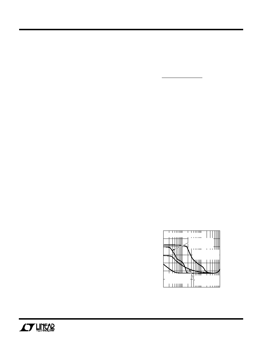
normal running voltage for the same reasons. Figure 5
shows minimum input voltage for a 3.3V output, both for
start-up and for normal operation. This graph indicates
that a 5V to 3.3V converter with 4.7V minimum input
voltage, will not start correctly below a 40mA load current
and will not run correctly below a 4mA load current. If
minimum load current is less than 50mA, a preload should
be added or the circuit in Figure 6 can be used.
LOAD CURRENT (mA)
1
INPUT
VOLTAGE
(V)
6.5
6.0
5.5
5.0
4.5
4.0
3.5
3.0
10
100
1000
LT1400 GXX
VALID ONLY FOR VOUT = 3.3V
MINIMUM VOLTAGE
TO START WITH
STANDARD CIRCUITS
MINIMUM VOLTAGE
TO START WITH
PNP ADDED
MINIMUM VOLTAGE
TO RUN WITH
STANDARD CIRCUIT
MINIMUM VOLTAGE
TO RUN WITH
PNP ADDED
MINIMUM VOLTAGE
TO RUN WITH
PNP ADDED
Figure 5. Minimum Input Voltage for VOUT = 3.3V
相关PDF资料 |
PDF描述 |
|---|---|
| LT1509IS | 2 A POWER FACTOR CONTROLLER WITH POST REGULATOR, PDSO20 |
| LT1509CS | 2 A POWER FACTOR CONTROLLER WITH POST REGULATOR, PDSO20 |
| LT1513CT7 | 5.4 A BATTERY CHARGE CONTROLLER, 580 kHz SWITCHING FREQ-MAX, PZFM7 |
| LT1576IS8#TR | 3.5 A SWITCHING REGULATOR, 240 kHz SWITCHING FREQ-MAX, PDSO8 |
| LT1634CMS8-2.5#PBF | 1-OUTPUT TWO TERM VOLTAGE REFERENCE, 2.5 V, PDSO8 |
相关代理商/技术参数 |
参数描述 |
|---|---|
| LT1508 | 制造商:LINER 制造商全称:Linear Technology 功能描述:Power Factor and PWM Controller(Voltage Mode) |
| LT1508C | 制造商:LINER 制造商全称:Linear Technology 功能描述:Power Factor and PWM Controller(Voltage Mode) |
| LT1508CN | 制造商:LINER 制造商全称:Linear Technology 功能描述:Power Factor and PWM Controller(Voltage Mode) |
| LT1508CSW | 功能描述:IC PWM/POWER FACTOR CNTRLR20SOIC RoHS:否 类别:集成电路 (IC) >> PMIC - PFC(功率因数修正) 系列:- 产品培训模块:GreenChip Synchronous Rectification Control Family of ICs 标准包装:1 系列:- 模式:间歇导电(DCM) 频率 - 开关:- 电流 - 启动:- 电源电压:8.6 V ~ 38 V 工作温度:-20°C ~ 150°C 安装类型:表面贴装 封装/外壳:14-SOIC(0.154",3.90mm 宽) 供应商设备封装:14-SO 包装:Digi-Reel® 其它名称:568-5348-6 |
| LT1508I | 制造商:LINER 制造商全称:Linear Technology 功能描述:Power Factor and PWM Controller(Voltage Mode) |
发布紧急采购,3分钟左右您将得到回复。