- 您现在的位置:买卖IC网 > PDF目录16302 > LT1513-2CR#PBF (Linear Technology)IC BATT CHRGR CONST/PROG I/V 7DD PDF资料下载
参数资料
| 型号: | LT1513-2CR#PBF |
| 厂商: | Linear Technology |
| 文件页数: | 11/16页 |
| 文件大小: | 0K |
| 描述: | IC BATT CHRGR CONST/PROG I/V 7DD |
| 标准包装: | 50 |
| 功能: | 充电管理 |
| 电池化学: | 所有电池类型 |
| 电源电压: | 2.7 V ~ 25 V |
| 工作温度: | 0°C ~ 125°C |
| 安装类型: | 表面贴装 |
| 封装/外壳: | TO-263-8,D²Pak(7 引线+接片),TO-263CA |
| 供应商设备封装: | D2PAK-7 |
| 包装: | 管件 |
| 产品目录页面: | 1340 (CN2011-ZH PDF) |
�� �
�
�LT1513/LT1513-2�
�APPLICATIO� N� S� I� N� FOR� M� ATIO� N�
�(from� the� Electrical� Characteristics).� Amplifier� output� resis-�
�tance� is� modeled� with� a� 330k� resistor.� The� power� stage�
�(modulator� section)� of� the� LT1513� is� modeled� as� a� transcon-�
�ductance� whose� value� is� 4(V� IN� )/(V� IN� +� V� BAT� ).� This� is� a� very�
�simplified� model� of� the� actual� power� stage,� but� it� is� sufficient�
�when� the� unity-gain� frequency� of� the� loop� is� low� compared�
�to� the� switching� frequency.� The� output� filter� capacitor� model�
�includes� its� ESR� (R� CAP� ).� A� series� resistance� (R� BAT� )� is� also�
�assigned� to� the� battery� model.�
�Analysis� of� this� loop� normally� shows� an� extremely� stable�
�system� for� all� conditions,� even� with� 0� ?� for� R5.� The� one�
�condition� which� can� cause� reduced� phase� margin� is� with� a�
�very� large� battery� resistance� (>5� ?� ),� or� with� the� battery�
�replaced� with� a� resistive� load.� The� addition� of� R5� gives� good�
�phase� margin� even� under� these� unusual� conditions.� R5�
�should� not� be� increased� above� 330� ?� without� checking� for�
�two� possible� problems.� The� first� is� instability� in� the� constant�
�current� region� (see� Constant-Current� Mode� Loop� Stability),�
�and� the� second� is� subharmonic� switching� where� switch� duty�
�cycle� varies� from� cycle� to� cycle.� This� duty� cycle� instability� is�
�caused� by� excess� switching� frequency� ripple� voltage� on� the�
�V� C� pin.� Normally� this� ripple� is� very� low� because� of� the�
�filtering� effect� of� C5,� but� large� values� of� R5� can� allow� high�
�ripple� on� the� V� C� pin.� Normal� loop� analysis� does� not� show� this�
�problem,� and� indeed� small� signal� loop� stability� can� be�
�excellent� even� in� the� presence� of� subharmonic� switching.�
�The� primary� issue� with� subharmonics� is� the� presence� of� EMI�
�at� frequencies� below� 500kHz.�
�Constant-Current� Mode� Loop� Stability�
�The� LT1513� is� normally� very� stable� when� operating� in� con-�
�stant-current� mode� (see� Figure� 7),� but� there� are� certain� con-�
�ditions� which� may� create� instabilities.� The� combination� of�
�higher� value� current� sense� resistors� (low� programmed� charg-�
�ing� current),� higher� input� voltages,� and� the� addition� of� a� loop�
�compensation� resistor� (R5)� on� the� V� C� pin� may� create� an� un-�
�stable� current� mode� loop.� (A� resistor� is� sometimes� added� in�
�series� with� C5� to� improve� loop� phase� margin� when� the� loop�
�is� operating� in� voltage� mode.)� Instability� results�
�because� loop� gain� is� too� high� in� the� 50kHz� to� 150kHz� region�
�where� excess� phase� occurs� in� the� current� sensing� amplifier�
�and� the� modulator.� The� I� FBA� amplifier� (gain� of� –12.5)� has� a�
�pole� at� approximately� 150kHz.� The� modulator� section� con-�
�sisting� of� the� current� comparator,� the� power� switch� and� the�
�magnetics,� has� a� pole� at� approximately� 50kHz� when� the�
�coupled� inductor� value� is� 10� μ� H.� Higher� inductance� will� reduce�
�the� pole� frequency� proportionally.� The� design� procedure� pre-�
�sented� here� is� to� roll� off� the� loop� to� unity-gain� at� a� frequency�
�of� 25kHz� or� lower� to� avoid� these� excess� phase� regions.�
�V1�
�MODULATOR� SECTION�
�I� P�
�FB�
�R� P� **�
�1M�
�C� P�
�3pF�
�I� P� =�
�4(V1)(V� IN� )�
�V� IN� +� V� BAT�
�R� A�
�I� FB�
�R4�
�24� ?�
�100k�
�V� C�
�I� FBA�
�R5�
�330� ?�
�C5�
�0.1� μ� F�
�R� G�
�330k�
�EA�
�g� m�
�1500� μ� mho�
�1.245V�
�C� A�
�10pF�
�VOLTAGE�
�GAIN� =� 12�
�C4�
�0.22� μ� F�
�R3�
�0.1� ?�
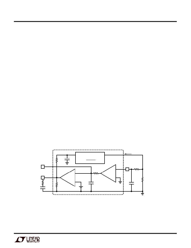
�THIS� IS� A� SIMPLIFIED� AC� MODEL� FOR� THE� LT1513� IN�
�CONSTANT-CURRENT� MODE.� RESISTOR� AND� CAPACITOR�
�NUMBERS� CORRESPOND� TO� THOSE� USED� IN� FIGURE� 1.�
�R� P� AND� C� P� MODEL� THE� PHASE� DELAY� IN� THE� PowerPath.�
�C3� IS� 3pF� FOR� A� 10� μ� H� INDUCTOR.� IT� SHOULD� BE� SCALED�
�PROPORTIONALLY� FOR� OTHER� INDUCTOR� VALUES� (6pF�
�FOR� 20� μ� H).� THE� PowerPath� IS� A� TRANSCONDUCTANCE�
�WHOSE� GAIN� IS� A� FUNCTION� OF� INPUT� AND� BATTERY�
�VOLTAGE� AS� SHOWN.�
�THE� CURRENT� AMPLIFIER� HAS� A� FIXED� VOLTAGE� GAIN� OF� 12.�
�ITS� PHASE� DELAY� IS� MODELED� WITH� R� A� AND� C� A� .�
�THE� ERROR� AMPLIFIER� HAS� A� TRANSCONDUCTANCE� OF�
�1500� μ� mho� AND� AN� INTERNAL� OUTPUT� SHUNT� RESISTANCE� OF�
�330k.�
�AS� SHOWN,� THIS� LOOP� HAS� A� UNITY-GAIN� FREQUENCY� OF�
�ABOUT� 27kHz.� R5� IS� NOT� USED� IN� ALL� APPLICATIONS,� BUT� IT�
�GIVES� BETTER� PHASE� MARGIN� IN� CONSTANT� VOLTAGE� MODE.�
�1513� F07�
�Figure� 7.� Constant-Current� Small-Signal� Model�
�sn1513� 1513fas�
�11�
�相关PDF资料 |
PDF描述 |
|---|---|
| LT1513-2CR | IC BATT CHRGR CONST/PROG I/V 7DD |
| LTC4008EGN-1#PBF | IC BATT CHARGER CTRLR 4A 20SSOP |
| M3BYK-1606R | IDC CABLE - MSR16K/MC16M/MPD16K |
| M1YXK-2436J | IDC CABLE - MPD24K/MC24G/X |
| LTC4006EGN-6#PBF | IC CHARGER BATTERY 4A 16-SSOP |
相关代理商/技术参数 |
参数描述 |
|---|---|
| LT1513-2CT7 | 功能描述:IC BATT CHG CNST/PROG I/V TO2207 RoHS:否 类别:集成电路 (IC) >> PMIC - 电池管理 系列:- 标准包装:1 系列:- 功能:充电管理 电池化学:锂离子(Li-Ion)、锂聚合物(Li-Pol) 电源电压:3.75 V ~ 6 V 工作温度:-40°C ~ 85°C 安装类型:表面贴装 封装/外壳:SC-74A,SOT-753 供应商设备封装:SOT-23-5 包装:剪切带 (CT) 产品目录页面:669 (CN2011-ZH PDF) 其它名称:MCP73831T-2ACI/OTCT |
| LT1513-2CT7#PBF | 功能描述:IC CUR-MODE SW-REG SEPIC T0220-7 RoHS:是 类别:集成电路 (IC) >> PMIC - 电池管理 系列:- 产品培训模块:Lead (SnPb) Finish for COTS Obsolescence Mitigation Program 标准包装:2,500 系列:- 功能:电池监控器 电池化学:碱性,锂离子,镍镉,镍金属氢化物 电源电压:1 V ~ 5.5 V 工作温度:-40°C ~ 85°C 安装类型:表面贴装 封装/外壳:SOT-23-6 供应商设备封装:SOT-6 包装:带卷 (TR) |
| LT1513-2IR | 功能描述:IC BATT CHRGR CONST/PROG I/V 7DD RoHS:否 类别:集成电路 (IC) >> PMIC - 电池管理 系列:- 产品培训模块:Lead (SnPb) Finish for COTS Obsolescence Mitigation Program 标准包装:2,500 系列:- 功能:电池监控器 电池化学:碱性,锂离子,镍镉,镍金属氢化物 电源电压:1 V ~ 5.5 V 工作温度:-40°C ~ 85°C 安装类型:表面贴装 封装/外壳:SOT-23-6 供应商设备封装:SOT-6 包装:带卷 (TR) |
| LT1513-2IR#PBF | 功能描述:IC BATT CHRGR CONST/PROG I/V 7DD RoHS:是 类别:集成电路 (IC) >> PMIC - 电池管理 系列:- 产品培训模块:Lead (SnPb) Finish for COTS Obsolescence Mitigation Program 标准包装:2,500 系列:- 功能:电池监控器 电池化学:碱性,锂离子,镍镉,镍金属氢化物 电源电压:1 V ~ 5.5 V 工作温度:-40°C ~ 85°C 安装类型:表面贴装 封装/外壳:SOT-23-6 供应商设备封装:SOT-6 包装:带卷 (TR) |
| LT1513-2IR#TR | 功能描述:IC CHARGER BATTERY FIXED V/I 7DD RoHS:否 类别:集成电路 (IC) >> PMIC - 电池管理 系列:- 产品培训模块:Lead (SnPb) Finish for COTS Obsolescence Mitigation Program 标准包装:2,500 系列:- 功能:电池监控器 电池化学:碱性,锂离子,镍镉,镍金属氢化物 电源电压:1 V ~ 5.5 V 工作温度:-40°C ~ 85°C 安装类型:表面贴装 封装/外壳:SOT-23-6 供应商设备封装:SOT-6 包装:带卷 (TR) |
发布紧急采购,3分钟左右您将得到回复。