- 您现在的位置:买卖IC网 > PDF目录16302 > LT1513-2CR#PBF (Linear Technology)IC BATT CHRGR CONST/PROG I/V 7DD PDF资料下载
参数资料
| 型号: | LT1513-2CR#PBF |
| 厂商: | Linear Technology |
| 文件页数: | 7/16页 |
| 文件大小: | 0K |
| 描述: | IC BATT CHRGR CONST/PROG I/V 7DD |
| 标准包装: | 50 |
| 功能: | 充电管理 |
| 电池化学: | 所有电池类型 |
| 电源电压: | 2.7 V ~ 25 V |
| 工作温度: | 0°C ~ 125°C |
| 安装类型: | 表面贴装 |
| 封装/外壳: | TO-263-8,D²Pak(7 引线+接片),TO-263CA |
| 供应商设备封装: | D2PAK-7 |
| 包装: | 管件 |
| 产品目录页面: | 1340 (CN2011-ZH PDF) |
�� �
�
�LT1513/LT1513-2�
�APPLICATIO� N� S� I� N� FOR� M� ATIO� N�
�The� LT1513� is� an� IC� battery� charger� chip� specifically� opti-�
�mized� to� use� the� SEPIC� converter� topology.� A� complete�
�charger� schematic� is� shown� in� Figure� 1.� The� SEPIC� topology�
�has� unique� advantages� for� battery� charging.� It� will� operate�
�with� input� voltages� above,� equal� to� or� below� the� battery�
�voltage,� has� no� path� for� battery� discharge� when� turned� off,�
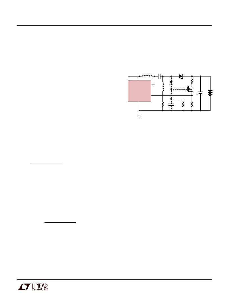
�Figure� 3.� D2,� C6� and� R6� form� a� peak� detector� to� drive� the� gate�
�of� the� FET� to� about� the� same� as� the� battery� voltage.� If� power�
�is� turned� off,� the� gate� will� drop� to� 0V� and� the� only� drain� on� the�
�battery� will� be� the� reverse� leakage� of� the� catch� diode� D1.� See�
�Diode� Selection� for� a� discussion� of� diode� leakage.�
�and� eliminates� the� snubber� losses� of� flyback� designs.� It� also�
�ADAPTER�
�L1A�
�C2�
�D1�
�has� a� current� sense� point� that� is� ground� referred� and� need�
�INPUT�
�not� be� connected� directly� to� the� battery.� The� two� inductors�
�shown� are� actually� just� two� identical� windings� on� one�
�inductor� core,� although� two� separate� inductors� can� be� used.�
�A� current� sense� voltage� is� generated� with� respect� to� ground�
�across� R3� in� Figure� 1.� The� average� current� through� R3� is�
�V� IN�
�LT1513�
�GND�
�V� SW�
�V� FB�
�L1B�
�R3�
�D2�
�C6�
�470pF�
�R6�
�470k�
�R1�
�R2�
�+�
�C1�
�always� identical� to� the� current� delivered� to� the� battery.� The�
�LT1513� current� limit� loop� will� servo� the� voltage� across� R3�
�to� –� 100mV� when� the� battery� voltage� is� below� the� voltage�
�limit� set� by� the� output� divider� R1/R2.� Constant-current�
�charging� is� therefore� set� at� 100mV/R3.� R4� and� C4� filter� the�
�SCHEMATIC� SIMPLIFIED� FOR� CLARITY�
�D2� =� 1N914,� 1N4148� OR� EQUIVALENT�
�Figure� 3.� Eliminating� Divider� Current�
�1513� F03�
�current� signal� to� deliver� a� smooth� feedback� voltage� to� the� I� FB�
�pin.� R1� and� R2� form� a� divider� for� battery� voltage� sensing� and�
�set� the� battery� float� voltage.� The� suggested� value� for� R2� is�
�12.4k.� R1� is� calculated� from:�
�Maximum� Input� Voltage�
�Maximum� input� voltage� for� the� LT1513� is� partly� determined�
�by� battery� voltage.� A� SEPIC� converter� has� a� maximum�
�R� 1� =�
�R2(V� BAT� – 1 .245)�
�1� .� 245� +� R� 2� (� 0� .� 3� μ� A� )�
�switch� voltage� equal� to� input� voltage� plus� output� voltage.�
�The� LT1513� has� a� maximum� input� voltage� of� 30V� and� a�
�maximum� switch� voltage� of� 40V,� so� this� limits� maximum�
�V� BAT� =� battery� float� voltage�
�0.3� μ� A� =� typical� FB� pin� bias� current�
�A� value� of� 12.4k� for� R2� sets� divider� current� at� 100� μ� A.� This� is�
�a� constant� drain� on� the� battery� when� power� to� the� charger� is�
�off.� If� this� drain� is� too� high,� R2� can� be� increased� to� 41.2k,�
�reducing� divider� current� to� 30� μ� A.� This� introduces� an� addi-�
�tional� uncorrectable� error� to� the� constant� voltage� float� mode�
�of� about� ±� 0.5%� as� calculated� by:�
�input� voltage� to� 30V,� or� 40V� –� V� BAT� ,� whichever� is� less.�
�Shutdown� and� Synchronization�
�The� dual� function� S/S� pin� provides� easy� shutdown� and�
�synchronization.� It� is� logic� level� compatible� and� can� be�
�pulled� high� or� left� floating� for� normal� operation.� A� logic� low�
�on� the� S/S� pin� activates� shutdown,� reducing� input� supply�
�current� to� 12� μ� A.� To� synchronize� switching,� drive� the� S/S� pin�
�V� BAT� Error� =�
�±� 0.15� μ� A(R1)(R2)�
�1.245(R1+� R2)�
�between� 600kHz� and� 800kHz.�
�Inductor� Selection�
�±� 0.15� μ� A� =� expected� variation� in� FB� bias� current� around� the�
�nominal� 0.3� μ� A� typical� value.�
�With� R2� =� 41.2k� and� R1� =� 228k,� (V� BAT� =� 8.2V),� the� error� due�
�to� variations� in� bias� current� would� be� ±� 0.42%.�
�A� second� option� is� to� disconnect� the� divider� when� charger�
�L1A� and� L1B� are� normally� just� two� identical� windings� on� one�
�core,� although� two� separate� inductors� can� be� used.� A� typical�
�value� is� 10� μ� H,� which� gives� about� 0.5A� peak-to-peak� induc-�
�tor� current.� Lower� values� will� give� higher� ripple� current,�
�which� reduces� maximum� charging� current.� 5� μ� H� can� be� used�
�if� charging� currents� are� at� least� 20%� lower� than� the� values�
�power� is� off.� This� can� be� done� with� a� small� NFET� as� shown� in�
�sn1513� 1513fas�
�7�
�相关PDF资料 |
PDF描述 |
|---|---|
| LT1513-2CR | IC BATT CHRGR CONST/PROG I/V 7DD |
| LTC4008EGN-1#PBF | IC BATT CHARGER CTRLR 4A 20SSOP |
| M3BYK-1606R | IDC CABLE - MSR16K/MC16M/MPD16K |
| M1YXK-2436J | IDC CABLE - MPD24K/MC24G/X |
| LTC4006EGN-6#PBF | IC CHARGER BATTERY 4A 16-SSOP |
相关代理商/技术参数 |
参数描述 |
|---|---|
| LT1513-2CT7 | 功能描述:IC BATT CHG CNST/PROG I/V TO2207 RoHS:否 类别:集成电路 (IC) >> PMIC - 电池管理 系列:- 标准包装:1 系列:- 功能:充电管理 电池化学:锂离子(Li-Ion)、锂聚合物(Li-Pol) 电源电压:3.75 V ~ 6 V 工作温度:-40°C ~ 85°C 安装类型:表面贴装 封装/外壳:SC-74A,SOT-753 供应商设备封装:SOT-23-5 包装:剪切带 (CT) 产品目录页面:669 (CN2011-ZH PDF) 其它名称:MCP73831T-2ACI/OTCT |
| LT1513-2CT7#PBF | 功能描述:IC CUR-MODE SW-REG SEPIC T0220-7 RoHS:是 类别:集成电路 (IC) >> PMIC - 电池管理 系列:- 产品培训模块:Lead (SnPb) Finish for COTS Obsolescence Mitigation Program 标准包装:2,500 系列:- 功能:电池监控器 电池化学:碱性,锂离子,镍镉,镍金属氢化物 电源电压:1 V ~ 5.5 V 工作温度:-40°C ~ 85°C 安装类型:表面贴装 封装/外壳:SOT-23-6 供应商设备封装:SOT-6 包装:带卷 (TR) |
| LT1513-2IR | 功能描述:IC BATT CHRGR CONST/PROG I/V 7DD RoHS:否 类别:集成电路 (IC) >> PMIC - 电池管理 系列:- 产品培训模块:Lead (SnPb) Finish for COTS Obsolescence Mitigation Program 标准包装:2,500 系列:- 功能:电池监控器 电池化学:碱性,锂离子,镍镉,镍金属氢化物 电源电压:1 V ~ 5.5 V 工作温度:-40°C ~ 85°C 安装类型:表面贴装 封装/外壳:SOT-23-6 供应商设备封装:SOT-6 包装:带卷 (TR) |
| LT1513-2IR#PBF | 功能描述:IC BATT CHRGR CONST/PROG I/V 7DD RoHS:是 类别:集成电路 (IC) >> PMIC - 电池管理 系列:- 产品培训模块:Lead (SnPb) Finish for COTS Obsolescence Mitigation Program 标准包装:2,500 系列:- 功能:电池监控器 电池化学:碱性,锂离子,镍镉,镍金属氢化物 电源电压:1 V ~ 5.5 V 工作温度:-40°C ~ 85°C 安装类型:表面贴装 封装/外壳:SOT-23-6 供应商设备封装:SOT-6 包装:带卷 (TR) |
| LT1513-2IR#TR | 功能描述:IC CHARGER BATTERY FIXED V/I 7DD RoHS:否 类别:集成电路 (IC) >> PMIC - 电池管理 系列:- 产品培训模块:Lead (SnPb) Finish for COTS Obsolescence Mitigation Program 标准包装:2,500 系列:- 功能:电池监控器 电池化学:碱性,锂离子,镍镉,镍金属氢化物 电源电压:1 V ~ 5.5 V 工作温度:-40°C ~ 85°C 安装类型:表面贴装 封装/外壳:SOT-23-6 供应商设备封装:SOT-6 包装:带卷 (TR) |
发布紧急采购,3分钟左右您将得到回复。