- 您现在的位置:买卖IC网 > PDF目录377707 > LT1571 (Linear Technology Corporation) Octal Bus Transceivers 20-SOIC 0 to 70 PDF资料下载
参数资料
| 型号: | LT1571 |
| 厂商: | Linear Technology Corporation |
| 英文描述: | Octal Bus Transceivers 20-SOIC 0 to 70 |
| 中文描述: | 恒流/恒压电池充电器预置电压和终止旗 |
| 文件页数: | 8/16页 |
| 文件大小: | 201K |
| 代理商: | LT1571 |
8
LT1571 Series
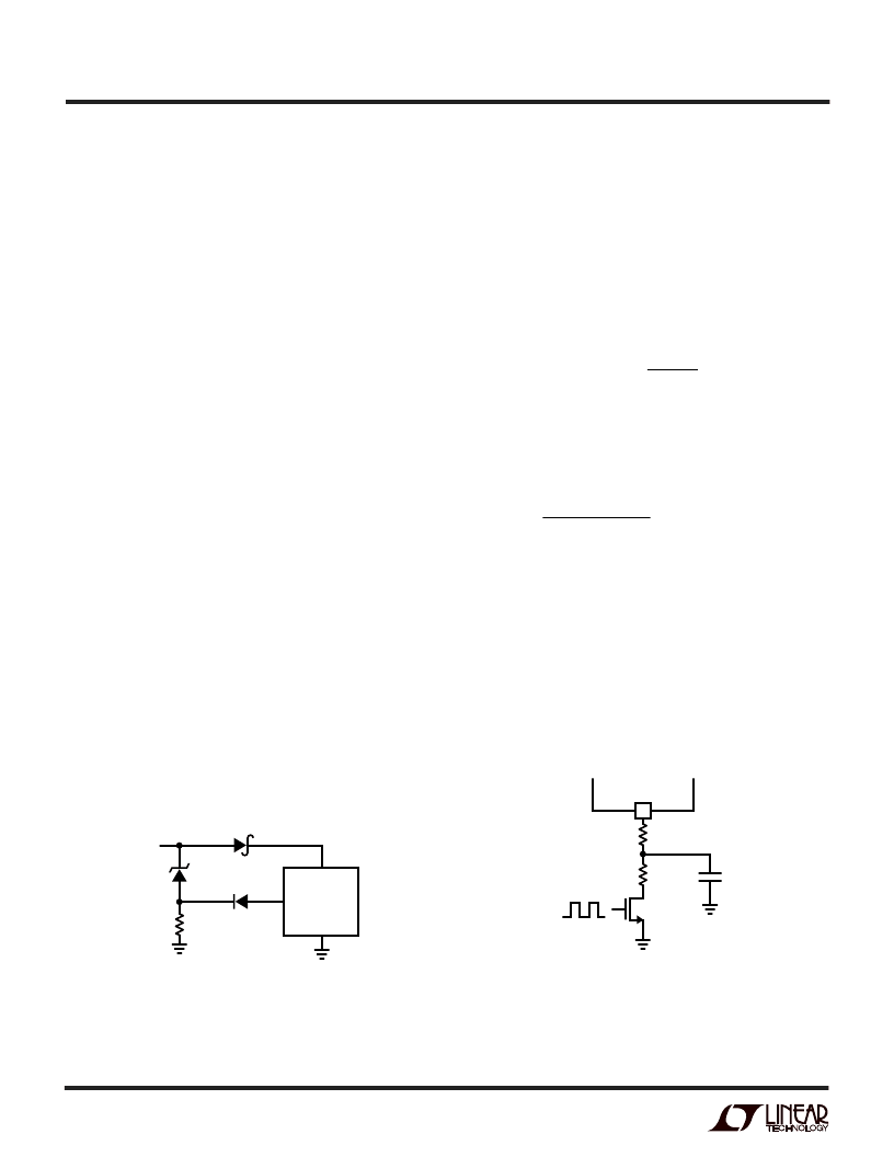
Figure 3. PWM Current Programming
is achieved with V
C
at 1.1V. With a 0.3
μ
F capacitor, the
time to reach full charge current is about 9ms and it is
assumed that input voltage to the charger will reach full
value in less than 3ms. Capacitance can be increased up to
1
μ
F if longer input start-up times are needed.
In any switching regulator, conventional time-based soft
starting can be defeated if the input voltage rises much
slower than the time-out period. This happens because the
switching regulators in the battery charger and the com-
puter power supply are typically supplying a fixed amount
of power to the load. If the input voltage comes up slowly
compared to the soft-start time, the regulators will try to
deliver full power to the load when the input voltage is still
well below its final value. If the adapter is current limited,
it cannot deliver full power at reduced output voltages and
the possibility exists for a quasi “latch” state where the
adapter output stays in a current limited state at reduced
output voltage. For instance, if maximum charger plus
computer load power is 20W, a 24V adapter might be
current limited at 1A. If adapter voltage is less than (20W/1A
= 20V) when full power is drawn, the adapter voltage will be
pulled down by the constant 20W load until it reaches a lower
stable state where the switching regulators can no longer
supply full load. This situation can be prevented by utilizing
undervoltage lockout set higher than the minimum adapter
voltage where full power can be achieved.
A fixed undervoltage lockout of 7V is built into the LT1571.
A higher lockout voltage can be implemented with a Zener
diode D2 (see Figure 2).
The lockout voltage will be V
IN
= V
Z
+ 1V.
For example, for a 24V adapter to start charging at 22V
IN
,
choose V
Z
= 21V. When V
IN
is less than 22V, D1 keeps V
C
low and charger off.
Charge Current Programming
The basic formula for charge current is (see Block
Diagram):
)
=
I
I
V
R
BAT
PROG
PROG
=
(
)(
(
)
2000
2 465
.
2000
where R
PROG
is the total resistance from PROG pin to
ground.
For example, 1A charge current is needed.
)(
2 465
2000
1
Charge current can also be programmed by pulse width
modulating I
PROG
with a switch Q1 to R
PROG
at a frequency
higher than a few kHz (Figure 3). Charge current will be
proportional to the duty cycle of Q1 with full current at
100% duty cycle.
When a microprocessor DAC output is used to control
charge current, it must be capable of sinking current
at a compliance up to 2.5V if connected directly to the
PROG pin.
R
V
A
k
PROG
=
(
)
=
4 93
.
.
Figure 2. Undervoltage Lockout
GND
V
CC
V
C
V
IN
1571 F02
LT1571
2k
D1
1N4148
D2
V
Z
D3
PWM
R
4.64k
300
PROG
C
PROG
1
μ
Q1
VN2222
5V
0V
LT1571
1571 F03
I
BAT
= (DC)(1A)
APPLICATIOU
W
U
U
相关PDF资料 |
PDF描述 |
|---|---|
| LT1572CS | 100kHz, 1.25A Switching Regulator with Catch Diode |
| LT1572 | 100kHz, 1.25A Switching Regulator with Catch Diode(100kHz, 1.25A 开关稳压器(带箝位二极管)) |
| LT1573C | Low Dropout PNP Regulator Driver |
| LT1573CS8 | Low Dropout PNP Regulator Driver |
| LT1573CS8-2.5 | Low Dropout PNP Regulator Driver |
相关代理商/技术参数 |
参数描述 |
|---|---|
| LT1571-1 | 制造商:LINER 制造商全称:Linear Technology 功能描述:Constant-Current/ Constant-Voltage Battery Charger with Preset Voltage and Termination Flag |
| LT-1571-111-012 | 制造商:Carling Technologies 功能描述:LT-SERIES TOGGLE SWITCH - Bulk |
| LT-1571-111-024 | 制造商:Carling Technologies 功能描述:SWITCH, TOGGLE, LTD, SP, 10A, ON-OFF-(ON) 制造商:Carling Technologies 功能描述:LT-SERIES TOGGLE SWITCH - Bulk |
| LT-1571-111-125 | 制造商:Carling Technologies 功能描述:LT-SERIES TOGGLE SWITCH - Bulk |
| LT-1571-112-125 | 制造商:Carling Technologies 功能描述:LT-SERIES TOGGLE SWITCH - Bulk |
发布紧急采购,3分钟左右您将得到回复。