- 您现在的位置:买卖IC网 > PDF目录377712 > LT1680ISW (LINEAR TECHNOLOGY CORP) High Power DC/DC Step-Up Controller PDF资料下载
参数资料
| 型号: | LT1680ISW |
| 厂商: | LINEAR TECHNOLOGY CORP |
| 元件分类: | 稳压器 |
| 英文描述: | High Power DC/DC Step-Up Controller |
| 中文描述: | SWITCHING CONTROLLER, 200 kHz SWITCHING FREQ-MAX, PDSO16 |
| 封装: | 0.300 INCH, PLASTIC, SOP-16 |
| 文件页数: | 12/16页 |
| 文件大小: | 322K |
| 代理商: | LT1680ISW |
12
LT1680
APPLICATIO
S I
FOR
ATIO
U
ments. Generally, the selection of inductor value can be
reduced to desired maximum ripple current in the inductor
(
I). For a boost converter, the minimum inductor value
for a given operating ripple current can be determined
using the following relation:
(
( )( )(
W
U
U
L
V
V
V
I f
V
MIN
IN
OUT
IN
O
OUT
=
)
)
–
Given an inductor value (L), the peak inductor current is
the sum of the average inductor current (I
AVG
) and half the
inductor ripple current (
I), or:
(
( )( )( )(
I
I
V
V
V
L f
V
PK
AVG
IN
2
OUT
IN
O
OUT
=
+
)
)
–
The inductor core type is determined by peak current and
efficiency requirements. The inductor core must with-
stand this peak current without saturating, and the series
winding resistance and core losses should be kept as
small as is practical to maximize conversion efficiency.
The LT1680 peak current threshold is 40% greater than
the average limit threshold. Slope compensation effects
reduce this margin as duty cycle increases. This margin
must be maintained to prevent peak current limit from
corrupting the programmed value for average current
limit. Programming the peak ripple current to less than
15% of the desired average current limit value will assure
proper operation of the average current limit feature
through 90% duty cycle (see Slope Compensation).
Slope Compensation
Current mode switching regulators that operate with a
duty cycle greater than 50% and have continuous inductor
current can exhibit duty cycle instability. While a regulator
will not be damaged and may even continue to function
acceptably during this type of subharmonic oscillation, an
irritating high-pitched squeal is usually produced.
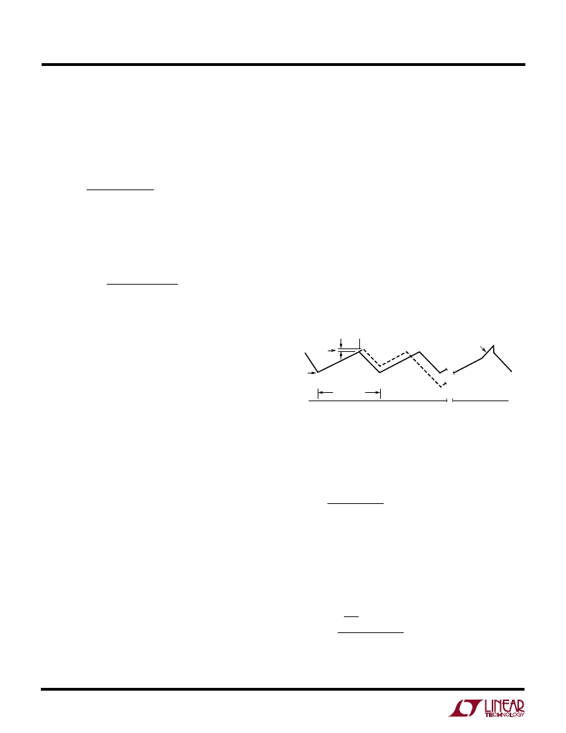
The criterion for current mode duty cycle instability is
met when the increasing slope of the inductor ripple
current is less than the decreasing slope, which is the
case at duty cycles greater than 50%. This condition is
illustrated in Figure 9a. The inductor ripple current starts
at I
1
, the beginning of each oscillator switch cycle.
Current increases at a rate S1 until the current reaches
the control trip level I
2
. The controller servo loop then
disables the switch and inductor current begins to de-
crease at a rate S2. If the current switch point (I
2
) is
perturbed slightly and increased by
I, the cycle time
ends such that the minimum current point is increased by
a factor of 1 + (S2/S1) to start the next cycle. On each
successive cycle, this error is multiplied by a factor of S2/
S1. Therefore, if S2/S1 is
≥
1, the system is unstable.
Subharmonic oscillations can be eliminated by augment-
ing the increasing ripple current slope (S1) in the control
loop. This is accomplished by adding an artificial ramp on
the inductor current waveform internal to the IC (with a
slope S
X
) as shown in Figure 9b. If the sum of the slopes
S1 + S
X
is greater than S2, this condition for subharmonic
oscillation no longer exists.
OSCILLATOR
PERIOD
TIME
0
0
a
b
I
T1
I
2
I
1
S1
S1
S2
S2
S1 + S
X
1680 F09
Figure 9. Inductor Current at DC > 50% and
Slope Compensation Adjusted Signal
For boost topologies, the required additional current wave-
form slope, or “Slope Compensation,” follows the relation:
X
≥
( )(
(
For duty cycles less than 50% (DC < 0.5), S
X
is negative and
is not required. For duty cycles greater than 50%, S
X
takes
on values dependent on S1 and duty cycle. S1 is simply V
IN
/
L. This leads to a minimum inductance requirement for a
given V
IN
, duty cycle and slope compensation (S
X
) of:
V
S
DC
1
–
S
DC
DC
)
)
1
1
–
–
L
DC
2
MIN
IN
X
=
(
)
1
–
The LT1680 contains an internal slope compensation
ramp that has an equivalent current referred value of:
相关PDF资料 |
PDF描述 |
|---|---|
| LT1680 | High Power DC/DC Step-Up Controller(大功率,DC/DC步升转换器) |
| LT1683IG | Ultralow Noise Push-Pull DC/DC Controller |
| LT1683 | Ultralow Noise Push-Pull DC/DC Controller |
| LT1683EG | Ultralow Noise Push-Pull DC/DC Controller |
| LT1719CS6 | 4.5ns Single/Dual Supply 3V/5V Comparator with Rail-to-Rail Output |
相关代理商/技术参数 |
参数描述 |
|---|---|
| LT1680ISW#PBF | 功能描述:IC REG CTRLR BST PWM CM 16-SOIC RoHS:是 类别:集成电路 (IC) >> PMIC - 稳压器 - DC DC 切换控制器 系列:- 特色产品:LM3753/54 Scalable 2-Phase Synchronous Buck Controllers 标准包装:1 系列:PowerWise® PWM 型:电压模式 输出数:1 频率 - 最大:1MHz 占空比:81% 电源电压:4.5 V ~ 18 V 降压:是 升压:无 回扫:无 反相:无 倍增器:无 除法器:无 Cuk:无 隔离:无 工作温度:-5°C ~ 125°C 封装/外壳:32-WFQFN 裸露焊盘 包装:Digi-Reel® 产品目录页面:1303 (CN2011-ZH PDF) 其它名称:LM3754SQDKR |
| LT1680ISW#TR | 功能描述:IC REG CTRLR BST PWM CM 16-SOIC RoHS:否 类别:集成电路 (IC) >> PMIC - 稳压器 - DC DC 切换控制器 系列:- 标准包装:4,500 系列:PowerWise® PWM 型:控制器 输出数:1 频率 - 最大:1MHz 占空比:95% 电源电压:2.8 V ~ 5.5 V 降压:是 升压:无 回扫:无 反相:无 倍增器:无 除法器:无 Cuk:无 隔离:无 工作温度:-40°C ~ 125°C 封装/外壳:6-WDFN 裸露焊盘 包装:带卷 (TR) 配用:LM1771EVAL-ND - BOARD EVALUATION LM1771 其它名称:LM1771SSDX |
| LT1680ISW#TRPBF | 功能描述:IC REG CTRLR BST PWM CM 16-SOIC RoHS:是 类别:集成电路 (IC) >> PMIC - 稳压器 - DC DC 切换控制器 系列:- 标准包装:4,500 系列:PowerWise® PWM 型:控制器 输出数:1 频率 - 最大:1MHz 占空比:95% 电源电压:2.8 V ~ 5.5 V 降压:是 升压:无 回扫:无 反相:无 倍增器:无 除法器:无 Cuk:无 隔离:无 工作温度:-40°C ~ 125°C 封装/外壳:6-WDFN 裸露焊盘 包装:带卷 (TR) 配用:LM1771EVAL-ND - BOARD EVALUATION LM1771 其它名称:LM1771SSDX |
| LT1681 | 制造商:LINER 制造商全称:Linear Technology 功能描述:Dual Transistor Synchronous Forward Controller |
| LT1681ESW | 功能描述:IC SYNCHRONOUS FWRD CTRLR 20SOIC RoHS:否 类别:集成电路 (IC) >> PMIC - 电源控制器,监视器 系列:- 产品培训模块:Lead (SnPb) Finish for COTS Obsolescence Mitigation Program 标准包装:2,500 系列:- 应用:多相控制器 输入电压:- 电源电压:9 V ~ 14 V 电流 - 电源:- 工作温度:-40°C ~ 85°C 安装类型:表面贴装 封装/外壳:40-WFQFN 裸露焊盘 供应商设备封装:40-TQFN-EP(5x5) 包装:带卷 (TR) |
发布紧急采购,3分钟左右您将得到回复。