- 您现在的位置:买卖IC网 > PDF目录1823 > LT1941EFE#TRPBF (Linear Technology)IC REG MULTI CONFIG TRPL 28TSSOP PDF资料下载
参数资料
| 型号: | LT1941EFE#TRPBF |
| 厂商: | Linear Technology |
| 文件页数: | 15/24页 |
| 文件大小: | 0K |
| 描述: | IC REG MULTI CONFIG TRPL 28TSSOP |
| 标准包装: | 2,000 |
| 类型: | 降压(降压),升压(升压),反相,Sepic |
| 输出类型: | 可调式 |
| 输出数: | 3 |
| 输出电压: | 1.25 V ~ 40 V |
| 输入电压: | 3.5 V ~ 25 V |
| PWM 型: | 电流模式 |
| 频率 - 开关: | 1.1MHz |
| 电流 - 输出: | 3A |
| 同步整流器: | 无 |
| 工作温度: | -40°C ~ 85°C |
| 安装类型: | 表面贴装 |
| 封装/外壳: | 28-SOIC(0.173",4.40mm 宽)裸露焊盘 |
| 包装: | 带卷 (TR) |
| 供应商设备封装: | 28-TSSOP 裸露焊盘 |
�� �
�
�LT1941�
�APPLICATIONS� INFORMATION�
�can� handle� at� least� 1.5A� of� current� without� saturating� and�
�ensure� that� the� inductor� has� a� low� DCR� (copper-wire� resis-�
�tance)� to� minimize� I� 2� R� power� losses.� If� using� uncoupled�
�inductors,� each� inductor� need� only� handle� one-half� of� the�
�total� switch� current� so� that� 0.75A� per� inductor� is� suf?cient.�
�A� 4.7μH� to� 15μH� coupled� inductor� or� two� 15μH� to� 20μH�
�uncoupled� inductors� will� usually� be� the� best� choice� for�
�most� LT1941� inverter� designs.� A� 4.7μH� to� 15μH� inductor�
�will� be� the� best� choice� for� most� LT1941� boost� designs.� In�
�this� case,� the� single� inductor� must� carry� the� entire� 1.5A�
�peak� switch� current.�
�exceeds� 20V,� use� the� UPS140� (a� 40V� diode).� These� diodes�
�are� rated� to� handle� an� average� forward� current� of� 1A.� For�
�applications� where� the� average� forward� current� of� the�
�diode� is� less� than� 0.5A,� use� an� ON� Semiconductor�
�MBR0520L� diode.� The� load� current� for� boost,� SEPIC� and�
�inverting� con?gurations� is� equal� to� the� average� diode�
�current.�
�BIAS2� Pin� Considerations�
�The� BIAS2� pin� provides� the� drive� current� for� the� inverter/�
�boost� switch.� The� voltage� source� on� the� BIAS2� line� should�
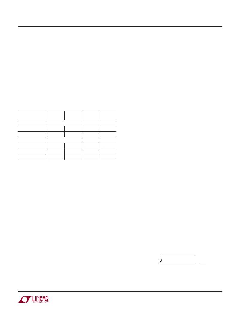
�Table� 4.� Inductors�
�PART� NUMBER�
�VALUE�
�(μH)�
�I� SAT(DC)�
�(A)�
�DCR�
�(Ω)�
�HEIGHT�
�(mm)�
�be� able� to� supply� the� rated� current� and� be� at� a� minimum�
�of� 2.5V.� For� highest� ef?ciency,� use� the� lowest� voltage�
�source� possible� (V� OUT� =� 3.3V,� for� example)� to� minimize�
�Coiltronics�
�the� V� BIAS2� ?� I� BIAS2� power� loss� inside� the� part.�
�TP3-4R7�
�4.7�
�1.5�
�0.181�
�2.2�
�TP4-100�
�Sumida�
�CDRH6D38NP-6R2�
�CDRH6D38NP-7R4�
�CDRH6D38NP-100�
�10�
�6.2�
�7.4�
�10�
�1.5�
�2.5�
�2.3�
�2.0�
�0.146�
�20m�
�23m�
�28m�
�3.0�
�3.8�
�3.8�
�3.8�
�INPUT� CAPACITOR� SELECTION�
�Bypass� the� input� of� the� LT1941� circuit� with� a� 10μF� or�
�higher� ceramic� capacitor� of� X7R� or� X5R� type.� A� lower�
�value� or� a� less� expensive� Y5V� type� will� work� if� there� is�
�additional� bypassing� provided� by� bulk� electrolytic� capaci-�
�Output� Capacitor� Selection�
�Use� low� ESR� (equivalent� series� resistance)� capacitors� at�
�the� output� to� minimize� the� output� ripple� voltage.� Multilayer�
�ceramic� capacitors� are� an� excellent� choice;� they� have� an�
�extremely� low� ESR� and� are� available� in� very� small� pack-�
�ages.� X7R� dielectrics� are� preferred,� followed� by� X5R,� as�
�these� materials� retain� their� capacitance� over� wide� voltage�
�and� temperature� ranges.� A� 4.7μF� to� 20μF� output� capacitor�
�is� suf?cient� for� most� LT1941� applications.� Solid� tantalum�
�or� OS-CON� capacitors� will� work� but� they� will� occupy� more�
�board� area� and� will� have� a� higher� ESR� than� a� ceramic�
�capacitor.� Always� use� a� capacitor� with� a� suf?cient� volt-�
�age� rating.�
�Diode� Selection�
�tors,� or� if� the� input� source� impedance� is� low.� The� following�
�paragraphs� describe� the� input� capacitor� considerations�
�in� more� detail.�
�Step-down� regulators� draw� current� from� the� input� sup-�
�ply� in� pulses� with� very� fast� rise� and� fall� times.� The� input�
�capacitor� is� required� to� reduce� the� resulting� voltage� ripple�
�at� the� LT1941� input� and� to� force� this� switching� current�
�into� a� tight� local� loop,� minimizing� EMI.� The� input� capaci-�
�tor� must� have� low� impedance� at� the� switching� frequency�
�to� do� this� effectively� and� it� must� have� an� adequate� ripple�
�current� rating.� With� two� switchers� operating� at� the� same�
�frequency� but� with� different� phases� and� duty� cycles,� cal-�
�culating� the� input� capacitor� RMS� current� is� not� simple;�
�however,� a� conservative� value� is� the� RMS� input� current�
�for� the� channel� that� is� delivering� the� most� power� (V� OUT�
�times� I� OUT� ):�
�A� Schottky� diode� is� recommended� for� use� with� the� LT1941�
�inverter/boost� regulator.� The� Microsemi� UPS120� is� a� very�
�good� choice.� Where� the� input� to� output� voltage� differential�
�C� IN� (� RMS� )� =� I� OUT� ?�
�V� OUT� (� V� IN� –� V� OUT� )�
�V� IN�
�<�
�I� OUT�
�2�
�1941fb�
�15�
�相关PDF资料 |
PDF描述 |
|---|---|
| LT1942EUF#TRPBF | IC REG SW QUAD TFT LCD 24-QFN |
| LT1943EFE#TRPBF | IC REG SW QUAD TFT LCD 28-TSSOP |
| LT1944-1EMS#TR | IC REG BST ADJ 0.1A/175MA 10MSOP |
| LT1945IMS#TRPBF | IC REG MULTI CONFIG ADJ 10MSOP |
| LT1946EMS8E#TRPBF | IC REG BOOST 1.5A 8MSOP |
相关代理商/技术参数 |
参数描述 |
|---|---|
| LT1942 | 制造商:LINER 制造商全称:Linear Technology 功能描述:Quad DCDC Converter for Triple Outputs TFT Supply Plus LED Driver |
| LT1942EUF | 制造商:Linear Technology 功能描述:Conv DC-DC Quad Inv/Step Up 2.6V to 16V 24-Pin QFN EP |
| LT1942EUF#PBF | 功能描述:IC REG SW QUAD TFT LCD 24-QFN RoHS:是 类别:集成电路 (IC) >> PMIC - 稳压器 - 专用型 系列:- 标准包装:43 系列:- 应用:控制器,Intel VR11 输入电压:5 V ~ 12 V 输出数:1 输出电压:0.5 V ~ 1.6 V 工作温度:-40°C ~ 85°C 安装类型:表面贴装 封装/外壳:48-VFQFN 裸露焊盘 供应商设备封装:48-QFN(7x7) 包装:管件 |
| LT1942EUF#TRPBF | 功能描述:IC REG SW QUAD TFT LCD 24-QFN RoHS:是 类别:集成电路 (IC) >> PMIC - 稳压器 - 专用型 系列:- 标准包装:43 系列:- 应用:控制器,Intel VR11 输入电压:5 V ~ 12 V 输出数:1 输出电压:0.5 V ~ 1.6 V 工作温度:-40°C ~ 85°C 安装类型:表面贴装 封装/外壳:48-VFQFN 裸露焊盘 供应商设备封装:48-QFN(7x7) 包装:管件 |
| LT1942EUFPBF | 制造商:Linear Technology 功能描述:Conv DC-DC Quad Inv/Step-Up 16V QFN24EP |
发布紧急采购,3分钟左右您将得到回复。