- 您现在的位置:买卖IC网 > PDF目录14147 > LT1944-1EMS#TRPBF (Linear Technology)IC REG BST ADJ 0.1A/175MA 10MSOP PDF资料下载
参数资料
| 型号: | LT1944-1EMS#TRPBF |
| 厂商: | Linear Technology |
| 文件页数: | 5/8页 |
| 文件大小: | 0K |
| 描述: | IC REG BST ADJ 0.1A/175MA 10MSOP |
| 标准包装: | 2,500 |
| 类型: | 升压(升压) |
| 输出类型: | 可调式 |
| 输出数: | 2 |
| 输出电压: | 1.23 V ~ 36 V |
| 输入电压: | 1.2 V ~ 15 V |
| 电流 - 输出: | 100mA,175mA |
| 同步整流器: | 无 |
| 工作温度: | -40°C ~ 85°C |
| 安装类型: | 表面贴装 |
| 封装/外壳: | 10-TFSOP,10-MSOP(0.118",3.00mm 宽) |
| 包装: | 带卷 (TR) |
| 供应商设备封装: | 10-MSOP |
�� �
�
�LT1944-1�
�APPLICATIO� S� I� FOR� ATIO�
�Choosing� an� Inductor�
�Several� recommended� inductors� that� work� well� with� the�
�LT1944-1� are� listed� in� Table� 1,� although� there� are� many�
�other� manufacturers� and� devices� that� can� be� used.� Con-�
�sult� each� manufacturer� for� more� detailed� information� and�
�for� their� entire� selection� of� related� parts.� Many� different�
�sizes� and� shapes� are� available.� Use� the� equations� and�
�recommendations� in� the� next� few� sections� to� find� the�
�correct� inductance� value� for� your� design.�
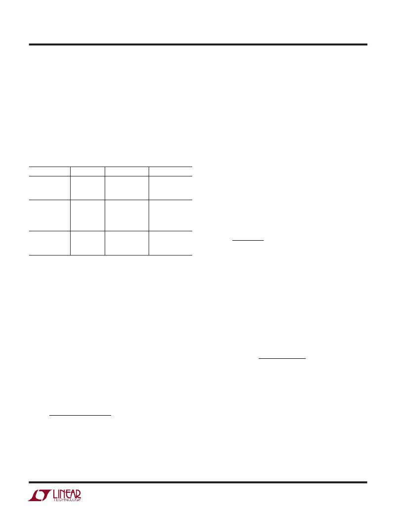
�Table� 1.� Recommended� Inductors�
�systems� with� output� voltages� below� 7V,� a� 10� μ� H� inductor�
�is� the� best� choice,� even� though� the� equation� above� might�
�specify� a� smaller� value.� This� is� due� to� the� inductor� current�
�overshoot� that� occurs� when� very� small� inductor� values� are�
�used� (see� Current� Limit� Overshoot� section).�
�For� higher� output� voltages,� the� formula� above� will� give�
�large� inductance� values.� For� a� 2V� to� 20V� converter� (typical�
�LCD� Bias� application),� a� 74� μ� H� inductor� is� called� for� with�
�the� above� equation,� but� a� 22� μ� H� inductor� could� be� used�
�without� excessive� reduction� in� maximum� output� current.�
�PART� VALUE� (� μ� H)� MAX� DCR� (� ?� )�
�LQH3C4R7� 4.7� 0.26�
�VENDOR�
�Murata�
�Inductor� Selection—SEPIC� Regulator�
�LQH3C100�
�LQH3C220�
�CD43-4R7�
�CD43-100�
�CDRH4D18-4R7�
�10�
�22�
�4.7�
�10�
�4.7�
�0.30�
�0.92�
�0.11�
�0.18�
�0.16�
�(714)� 852-2001�
�www.murata.com�
�Sumida�
�(847)� 956-0666�
�www.sumida.com�
�The� formula� below� calculates� the� approximate� inductor�
�value� to� be� used� for� a� SEPIC� regulator� using� the� LT1944-1.�
�As� for� the� boost� inductor� selection,� a� larger� or� smaller�
�value� can� be� used.�
�L� =� 2� ?� OUT� D�
�?� t� OFF�
�CDRH4D18-100�
�DO1608-472�
�DO1608-103�
�DO1608-223�
�10�
�4.7�
�10�
�22�
�0.20�
�0.09�
�0.16�
�0.37�
�Coilcraft�
�(847)� 639-6400�
�www.coilcraft.com�
�?� V� +� V�
�?� I� LIM�
�?�
�?�
�I� PEAK� =� I� LIM� +� ?�
�?� 100� ns�
�Inductor Selection—Boost Regulator�
�The� formula� below� calculates� the� appropriate� inductor�
�value� to� be� used� for� a� boost� regulator� using� the� LT1944-1�
�(or� at� least� provides� a� good� starting� point).� This� value�
�provides� a� good� tradeoff� in� inductor� size� and� system�
�performance.� Pick� a� standard� inductor� close� to� this� value.�
�A� larger� value� can� be� used� to� slightly� increase� the� available�
�output� current,� but� limit� it� to� around� twice� the� value�
�calculated� below,� as� too� large� of� an� inductance� will� in-�
�crease� the� output� voltage� ripple� without� providing� much�
�additional� output� current.� A� smaller� value� can� be� used�
�(especially� for� systems� with� output� voltages� greater� than�
�12V)� to� give� a� smaller� physical� size.� Inductance� can� be�
�calculated� as:�
�Current� Limit� Overshoot�
�For� the� constant� off-time� control� scheme� of� the� LT1944-1,�
�the� power� switch� is� turned� off� only� after� the� current� limit�
�is� reached.� There� is� a� 100ns� delay� between� the� time� when�
�the� current� limit� is� reached� and� when� the� switch� actually�
�turns� off.� During� this� delay,� the� inductor� current� exceeds�
�the� current� limit� by� a� small� amount.� The� peak� inductor�
�current� can� be� calculated� by:�
�?� V� IN(MAX)� ?� V� SAT� ?�
�?� L� ?�
�Where� V� SAT� =� 0.25V� (switch� saturation� voltage).� The�
�current� overshoot� will� be� most� evident� for� systems� with�
�V� OUT� ?� V� IN� (� )� +� V� D�
�L� =�
�MIN�
�I� LIM�
�t� OFF�
�high� input� voltages� and� for� systems� where� smaller� induc-�
�tor� values� are� used.� This� overshoot� can� be� beneficial� as� it�
�helps� increase� the� amount� of� available� output� current� for�
�smaller� inductor� values.� This� will� be� the� peak� current� seen�
�where� V� D� =� 0.4V� (Schottky� diode� voltage),� I� LIM� =� 100mA�
�(or� 175mA)� and� t� OFF� =� 400ns� (or� 1.5� μ� s);� for� designs� with�
�varying� V� IN� such� as� battery� powered� applications,� use� the�
�minimum� V� IN� value� in� the� above� equation.� For� most�
�by� the� inductor� (and� the� diode)� during� normal� operation.�
�For� designs� using� small� inductance� values� (especially� at�
�input� voltages� greater� than� 5V),� the� current� limit� over-�
�shoot� can� be� quite� high.� Although� it� is� internally� current�
�5�
�相关PDF资料 |
PDF描述 |
|---|---|
| CGS154ULX5L3PD | CAP ALUM 150000UF 40V SCREW |
| CGH152T500V5C | CAP ALUM 1500UF 500V SCREW |
| LQR2G562MSEH | CAP ALUM 5600UF 400V 20% SCREW |
| LQR2G562MSEG | CAP ALUM 5600UF 400V 20% SCREW |
| CGS602T300X8L | CAP ALUM 6000UF 300V SCREW |
相关代理商/技术参数 |
参数描述 |
|---|---|
| LT1944EMS | 功能描述:IC REG BOOST ADJ 0.35A DL 10MSOP RoHS:否 类别:集成电路 (IC) >> PMIC - 稳压器 - DC DC 开关稳压器 系列:- 标准包装:2,500 系列:- 类型:升压(升压) 输出类型:可调式 输出数:1 输出电压:1.24 V ~ 30 V 输入电压:1.5 V ~ 12 V PWM 型:电流模式,混合 频率 - 开关:600kHz 电流 - 输出:500mA 同步整流器:无 工作温度:-40°C ~ 85°C 安装类型:表面贴装 封装/外壳:8-SOIC(0.154",3.90mm 宽) 包装:带卷 (TR) 供应商设备封装:8-SOIC |
| LT1944EMS#PBF | 功能描述:IC REG BOOST ADJ 0.35A DL 10MSOP RoHS:是 类别:集成电路 (IC) >> PMIC - 稳压器 - DC DC 开关稳压器 系列:- 标准包装:250 系列:- 类型:降压(降压) 输出类型:固定 输出数:1 输出电压:1.2V 输入电压:2.05 V ~ 6 V PWM 型:电压模式 频率 - 开关:2MHz 电流 - 输出:500mA 同步整流器:是 工作温度:-40°C ~ 85°C 安装类型:表面贴装 封装/外壳:6-UFDFN 包装:带卷 (TR) 供应商设备封装:6-SON(1.45x1) 产品目录页面:1032 (CN2011-ZH PDF) 其它名称:296-25628-2 |
| LT1944EMS#TR | 功能描述:IC REG BOOST ADJ 0.35A DL 10MSOP RoHS:否 类别:集成电路 (IC) >> PMIC - 稳压器 - DC DC 开关稳压器 系列:- 标准包装:2,500 系列:- 类型:升压(升压) 输出类型:可调式 输出数:1 输出电压:1.24 V ~ 30 V 输入电压:1.5 V ~ 12 V PWM 型:电流模式,混合 频率 - 开关:600kHz 电流 - 输出:500mA 同步整流器:无 工作温度:-40°C ~ 85°C 安装类型:表面贴装 封装/外壳:8-SOIC(0.154",3.90mm 宽) 包装:带卷 (TR) 供应商设备封装:8-SOIC |
| LT1944EMS#TRPBF | 功能描述:IC REG BOOST ADJ 0.35A DL 10MSOP RoHS:是 类别:集成电路 (IC) >> PMIC - 稳压器 - DC DC 开关稳压器 系列:- 标准包装:2,500 系列:- 类型:升压(升压) 输出类型:可调式 输出数:1 输出电压:1.24 V ~ 30 V 输入电压:1.5 V ~ 12 V PWM 型:电流模式,混合 频率 - 开关:600kHz 电流 - 输出:500mA 同步整流器:无 工作温度:-40°C ~ 85°C 安装类型:表面贴装 封装/外壳:8-SOIC(0.154",3.90mm 宽) 包装:带卷 (TR) 供应商设备封装:8-SOIC |
| LT1944EMSPBF | 制造商:Linear Technology 功能描述:Conv DC-DC Dual Step-Up 1.2-15V MSOP10 |
发布紧急采购,3分钟左右您将得到回复。