- 您现在的位置:买卖IC网 > PDF目录80082 > LT3407EDD-2 (LINEAR TECHNOLOGY CORP) 1.6 A DUAL SWITCHING CONTROLLER, 2700 kHz SWITCHING FREQ-MAX, PDSO10 PDF资料下载
参数资料
| 型号: | LT3407EDD-2 |
| 厂商: | LINEAR TECHNOLOGY CORP |
| 元件分类: | 稳压器 |
| 英文描述: | 1.6 A DUAL SWITCHING CONTROLLER, 2700 kHz SWITCHING FREQ-MAX, PDSO10 |
| 封装: | 3 X 3 MM, PLASTIC, MO-229WEED-2, DFN-10 |
| 文件页数: | 16/16页 |
| 文件大小: | 221K |
| 代理商: | LT3407EDD-2 |
LTC3407-2
9
34072fa
capacitors, such as Sanyo POSCAP, Panasonic Special
Polymer (SP), and Kemet A700, offer very low ESR, but
have a lower capacitance density than other types. Tanta-
lum capacitors have the highest capacitance density, but
they have a larger ESR and it is critical that the capacitors
are surge tested for use in switching power supplies. An
excellent choice is the AVX TPS series of surface mount
tantalums, available in case heights ranging from 2mm to
4mm. Aluminum electrolytic capacitors have a signifi-
cantly larger ESR, and are often used in extremely cost-
sensitive applications provided that consideration is given
to ripple current ratings and long term reliability. Ceramic
capacitors have the lowest ESR and cost, but also have the
lowest capacitance density, a high voltage and tempera-
ture coefficient, and exhibit audible piezoelectric effects.
In addition, the high Q of ceramic capacitors along with
trace inductance can lead to significant ringing.
In most cases, 0.1
μF to 1μF of ceramic capacitors should
also be placed close to the LTC3407-2 in parallel with the
main capacitors for high frequency decoupling.
Ceramic Input and Output Capacitors
Higher value, lower cost ceramic capacitors are now
becoming available in smaller case sizes. These are tempt-
ing for switching regulator use because of their very low
ESR. Unfortunately, the ESR is so low that it can cause
loop stability problems. Solid tantalum capacitor ESR
generates a loop “zero” at 5kHz to 50kHz that is instrumen-
tal in giving acceptable loop phase margin. Ceramic ca-
pacitors remain capacitive to beyond 300kHz and usually
resonate with their ESL before ESR becomes effective.
Also, ceramic caps are prone to temperature effects which
APPLICATIO S I FOR ATIO
WU
U
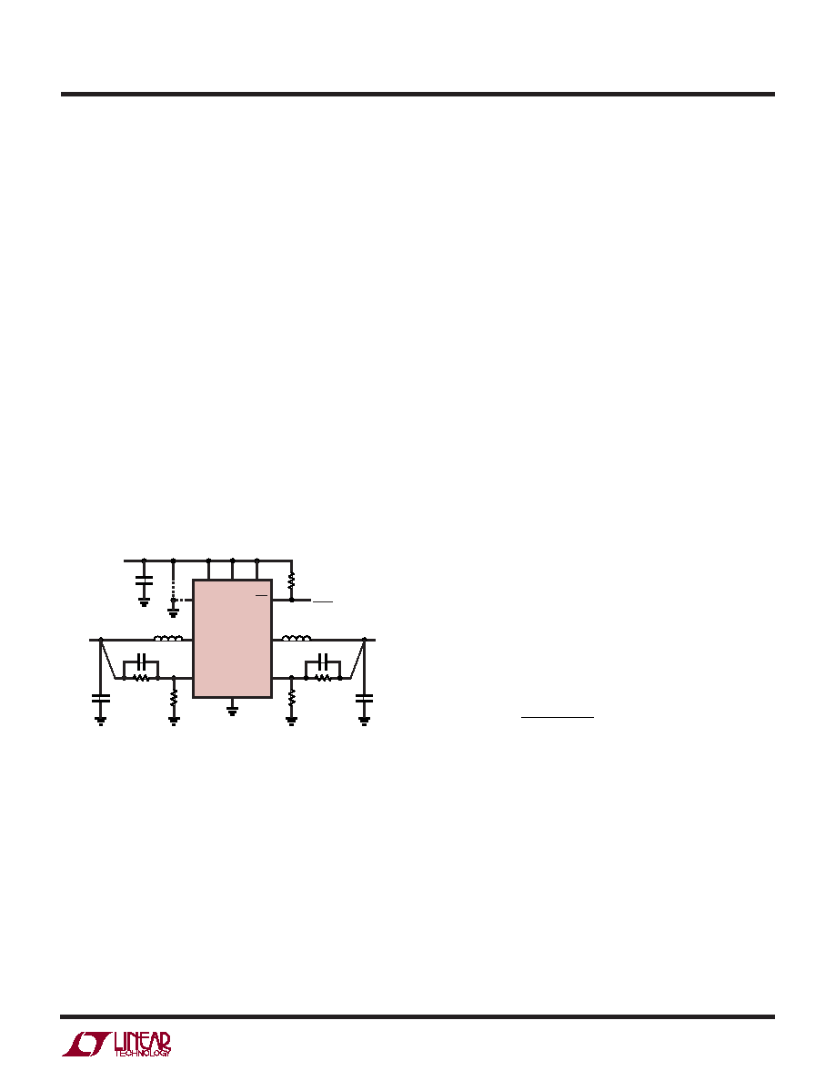
Figure 2. LTC3407-2 General Schematic
RUN2
VIN
VIN = 2.5V
TO 5.5V
VOUT2
VOUT1
RUN1
POR
SW1
VFB1
GND
VFB2
SW2
MODE/SYNC
LTC3407-2
CIN
R5
POWER-ON
RESET
C4
C5
L1
L2
R4
R2
R1
R3
COUT2
COUT1
3407 F02
PS*
BM*
*MODE/SYNC = 0V: PULSE SKIP
MODE/SYNC = VIN: Burst Mode
requires the designer to check loop stability over the
operating temperature range. To minimize their large
temperature and voltage coefficients, only X5R or X7R
ceramic capacitors should be used. A good selection of
ceramic capacitors is available from Taiyo Yuden, AVX,
Kemet, TDK, and Murata.
Great care must be taken when using only ceramic input
and output capacitors. When a ceramic capacitor is used
at the input and the power is being supplied through long
wires, such as from a wall adapter, a load step at the output
can induce ringing at the VIN pin. At best, this ringing can
couple to the output and be mistaken as loop instability. At
worst, the ringing at the input can be large enough to
damage the part.
Since the ESR of a ceramic capacitor is so low, the input
and output capacitor must instead fulfill a charge storage
requirement. During a load step, the output capacitor must
instantaneously supply the current to support the load
until the feedback loop raises the switch current enough to
support the load. The time required for the feedback loop
to respond is dependent on the compensation and the
output capacitor size. Typically, 3-4 cycles are required to
respond to a load step, but only in the first cycle does the
output drop linearly. The output droop, VDROOP, is usually
about 2-3 times the linear drop of the first cycle. Thus, a
good place to start is with the output capacitor size of
approximately:
C
I
fV
OUT
O
DROOP
≈
Δ
25
.
More capacitance may be required depending on the duty
cycle and load step requirements.
In most applications, the input capacitor is merely re-
quired to supply high frequency bypassing, since the
impedance to the supply is very low. A 10
μF ceramic
capacitor is usually enough for these conditions.
Setting the Output Voltage
The LTC3407-2 develops a 0.6V reference voltage be-
tween the feedback pin, VFB, and the ground as shown in
Figure 2. The output voltage is set by a resistive divider
according to the following formula:
相关PDF资料 |
PDF描述 |
|---|---|
| LT3407EMSE-2 | 1.6 A DUAL SWITCHING CONTROLLER, 2700 kHz SWITCHING FREQ-MAX, PDSO10 |
| LES25A48-2V5RAJ | 1-OUTPUT 62.5 W DC-DC REG PWR SUPPLY MODULE |
| LES25A48-3V3RAJ | 1-OUTPUT 82.5 W DC-DC REG PWR SUPPLY MODULE |
| LT3467AIS67#TR | 2.5 A SWITCHING REGULATOR, 2700 kHz SWITCHING FREQ-MAX, PDSO6 |
| LKP5660-5EPD6TB1 | 2-OUTPUT 250 W AC-DC PWR FACTOR CORR MODULE |
相关代理商/技术参数 |
参数描述 |
|---|---|
| LT340Z | 制造商:SEOUL 制造商全称:Seoul Semiconductor 功能描述:GREEN OVAL LAMP LED |
| LT341 | 制造商:SEOUL 制造商全称:Seoul Semiconductor 功能描述:BLUE OVAL LAMP LED |
| LT3412G | 制造商:未知厂家 制造商全称:未知厂家 功能描述:Optoelectronic |
| LT341BC | 制造商:Datak Corporation 功能描述: |
| LT341L | 制造商:未知厂家 制造商全称:未知厂家 功能描述:Optoelectronic |
发布紧急采购,3分钟左右您将得到回复。