- 您现在的位置:买卖IC网 > PDF目录80080 > LT3500IMSE#PBF (LINEAR TECHNOLOGY CORP) 3.5 A SWITCHING REGULATOR, 2800 kHz SWITCHING FREQ-MAX, PDSO16 PDF资料下载
参数资料
| 型号: | LT3500IMSE#PBF |
| 厂商: | LINEAR TECHNOLOGY CORP |
| 元件分类: | 稳压器 |
| 英文描述: | 3.5 A SWITCHING REGULATOR, 2800 kHz SWITCHING FREQ-MAX, PDSO16 |
| 封装: | LEAD FREE, PLASTIC, MSOP-16 |
| 文件页数: | 11/28页 |
| 文件大小: | 318K |
| 代理商: | LT3500IMSE#PBF |
第1页第2页第3页第4页第5页第6页第7页第8页第9页第10页当前第11页第12页第13页第14页第15页第16页第17页第18页第19页第20页第21页第22页第23页第24页第25页第26页第27页第28页
LT3500
19
3500fc
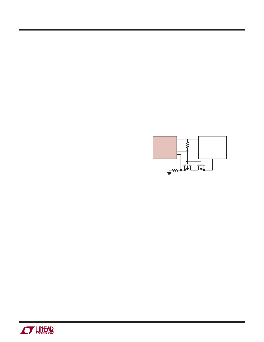
Figure 7. Synchronous Signal Powered from Regulator’s Output
LT3500
SYNCHRONIZATION
CIRCUITRY
LDRV
PG
RT/SYNC
3500 F07
VCC
CLK
current proportional to the voltage at the VC pin. Note that
the output capacitor integrates this current, and that the
capacitor on the VC pin (CC) integrates the error amplier
output current, resulting in two poles in the loop. In
most cases a zero is required and comes from either the
output capacitor ESR or from a resistor in series with CC.
This simple model works well as long as the value of the
inductor is not too high and the loop crossover frequency
is much lower than the switching frequency. A phase lead
capacitor (CPL) across the feedback divider may improve
the transient response.
Synchronization
The RT/SYNC pin can be used to synchronize the LT3500
to an external clock source. Driving the RT/SYNC resistor
with a clock source triggers the synchronization detection
circuitry. Once synchronization is detected, the rising edge
of SW will be synchronized to the rising edge of the RT/SYNC
pin signal. An AGC loop will adjust slope compensation
to avoid subharmonic oscillation.
The synchronizing clock signal input to the LT3500 must
have a frequency between 250kHz and 2.5MHz, a duty
cycle between 20% and 80%, a low state below 0.5V and
a high state above 1.6V. Synchronization signals outside
of these parameters will cause erratic switching behavior.
The RT/SYNC resistor should be set such that the free
running frequency ((VRT/SYNC – VSYNCLO)/RRT/SYNC) is
approximately equal to the synchronization frequency. If
the synchronization signal is halted, the synchronization
detection circuitry will timeout in typically 10μs at which
time the LT3500 reverts to the free-running frequency based
on the current through RT/SYNC. If the RT/SYNC pin is held
above 1.1V at any time, switching will be disabled.
If the synchronization signal is not present during regu-
lator start-up (for example, the synchronization circuitry
is powered from the regulator output) the RT/SYNC pin
must see an equivalent resistance to ground between 15k
and 200k until the synchronization circuitry is active for
proper start-up operation.
If the synchronization signal powers up in an undetermined
state (VOL, VOH, Hi-Z), connect the synchronization clock
to the LT3500 as shown in Figure 7. The circuit as shown
will isolate the synchronization signal when the output
voltage is below 90% of the regulated output. The LT3500
will start-up with a switching frequency determined by the
resistor from the RT/SYNC pin to ground.
APPLICATIONS INFORMATION
If the synchronization signal powers up in a low impedance
state (VOL), connect a resistor between the RT/SYNC pin
and the synchronizing clock. The equivalent resistance
seen from the RT/SYNC pin to ground will set the start-up
frequency.
If the synchronization signal powers up in a high impedance
state (Hi-Z), connect a resistor from the RT/SYNC pin to
ground. The equivalent resistance seen from the RT/SYNC
pin to ground will set the start-up frequency.
相关PDF资料 |
PDF描述 |
|---|---|
| LWN1801-6EM1FK2G | DC-DC REG PWR SUPPLY MODULE |
| LWN1801-6EM2FK2G | DC-DC REG PWR SUPPLY MODULE |
| LT1304CS8-5#PBF | 1.2 A SWITCHING REGULATOR, 300 kHz SWITCHING FREQ-MAX, PDSO8 |
| LX1004CDM-2.5-TR | 1-OUTPUT TWO TERM VOLTAGE REFERENCE, 2.5 V, PDSO8 |
| LT3574EMS#TRPBF | 1.1 A SWITCHING REGULATOR, 1000 kHz SWITCHING FREQ-MAX, PDSO16 |
相关代理商/技术参数 |
参数描述 |
|---|---|
| LT3500IMSE-TRPBF | 制造商:LINER 制造商全称:Linear Technology 功能描述:Monolithic 2A Step-Down Regulator Plus Linear Regulator/Controller |
| LT3500T | 制造商:Eaton Corporation 功能描述:TYPE LT TRIP UNIT ONLY 3P 500A 600VAC MAX |
| LT3501 | 制造商:LINER 制造商全称:Linear Technology 功能描述:Monolithic Dual Tracking 3A Step-Down Switching Regulator |
| LT3501_12 | 制造商:LINER 制造商全称:Linear Technology 功能描述:Monolithic Dual Tracking 3A Step-Down Switching |
| LT3501EFE | 制造商:Linear Technology 功能描述:Conv DC-DC Dual Step Down 3.1V to 25V 20-Pin TSSOP EP |
发布紧急采购,3分钟左右您将得到回复。