- 您现在的位置:买卖IC网 > PDF目录1825 > LT3575IFE#TRPBF (Linear Technology)IC REG FLYBACK ISO ADJ 16TSSOP PDF资料下载
参数资料
| 型号: | LT3575IFE#TRPBF |
| 厂商: | Linear Technology |
| 文件页数: | 9/24页 |
| 文件大小: | 0K |
| 描述: | IC REG FLYBACK ISO ADJ 16TSSOP |
| 标准包装: | 2,500 |
| 类型: | 回扫,隔离 |
| 输出类型: | 可调式 |
| 输出数: | 1 |
| 输出电压: | 可调至 60V |
| 输入电压: | 3 V ~ 40 V |
| PWM 型: | 电流模式,混合 |
| 频率 - 开关: | 1MHz |
| 电流 - 输出: | 2.5A |
| 同步整流器: | 无 |
| 工作温度: | -40°C ~ 125°C |
| 安装类型: | 表面贴装 |
| 封装/外壳: | 16-TSSOP(0.173",4.40mm)裸露焊盘 |
| 包装: | 带卷 (TR) |
| 供应商设备封装: | 16-TSSOP-EP |
| 配用: | 732-3306-ND - BOARD EVAL FOR LT3575 |
| 相关产品: | 732-2669-2-ND - TRANS FLYBACK LT3748 20UH SMD 732-2669-6-ND - TRANS FLYBACK LT3748 20UH SMD 732-2668-6-ND - TRANS FLYBACK LT3748 14UH SMD 732-2667-6-ND - TRANS FLYBACK LT3748 500UH SMD 732-2666-6-ND - TRANS FLYBACK LT3748 12UH SMD 732-2665-6-ND - TRANS FLYBACK LT3748 12UH SMD 732-2664-6-ND - TRANS FLYBACK LT3748 15UH SMD 732-2663-6-ND - TRANS FLYBACK LT3748 15UH SMD 732-2662-6-ND - TRANS FLYBACK LT3748 8UH SMD 732-2661-6-ND - TRANS FLYBACK LT3748 8UH SMD 更多... |
�� �
�
�LT3575�
�APPLICATIONS� INFORMATION�
�ERROR� AMPLIFIER—DYNAMIC� THEORY�
�Due� to� the� sampling� nature� of� the� feedback� loop,� there�
�are� several� timing� signals� and� other� constraints� that� are�
�Selecting� R� FB� and� R� REF� Resistor� Values�
�The� expression� for� V� OUT,� developed� in� the� Operation� section,�
�can� be� rearranged� to� yield� the� following� expression� for� R� FB� :�
�R� REF� PS� ??� (� V� OUT� +� V� F� )� α� +� V� TC� ??�
�required for proper LT3575 operation.�
�Minimum� Current� Limit�
�R� FB� =�
�?� N�
�V� BG�
�The� LT3575� obtains� output� voltage� information� from� the�
�SW� pin� when� the� secondary� winding� conducts� current.�
�The� sampling� circuitry� needs� a� minimum� amount� of� time�
�to� sample� the� output� voltage.� To� guarantee� enough� time,�
�a� minimum� inductance� value� must� be� maintained.� The�
�primary� side� magnetizing� inductance� must� be� chosen�
�above� the� following� value:�
�where,�
�V� OUT� =� Output� voltage�
�V� F� =� Switching� diode� forward� voltage�
�α� =� Ratio� of� Q1,� IC� to� IE,� typically� 0.986�
�N� PS� =� Effective� primary-to-secondary� turns� ratio�
�?� N� PS� =� V� OUT� ?� N� PS� ?� ?�
�?�
�?�
�?�
�L� PRI� ≥� V� OUT� ?�
�t� MIN�
�I� MIN�
�?� 0 . 88μH� ?�
�V�
�V� TC� =� 0.55V�
�The� equation� assumes� the� temperature� coef?cients� of�
�t� MIN� =� minimum� off-time,� 350ns�
�I� MIN� =� minimum� current� limit,� 400mA�
�The� minimum� current� limit� is� higher� than� that� on� the� Elec-�
�trical� Characteristics� table� due� to� the� overshoot� caused� by�
�the� comparator� delay.�
�Leakage� Inductance� Blanking�
�When� the� output� switch� ?rst� turns� off,� the� ?yback� pulse�
�appears.� However,� it� takes� a� ?nite� time� until� the� transformer�
�primary� side� voltage� waveform� approximately� represents�
�the� output� voltage.� This� is� partly� due� to� the� rise� time� on�
�the� SW� node,� but� more� importantly� due� to� the� trans-�
�former� leakage� inductance.� The� latter� causes� a� very� fast�
�voltage� spike� on� the� primary� side� of� the� transformer� that�
�is� not� directly� related� to� output� voltage� (some� time� is� also�
�required� for� internal� settling� of� the� feedback� ampli?er�
�circuitry).� The� leakage� inductance� spike� is� largest� when�
�the� power� switch� current� is� highest.�
�In� order� to� maintain� immunity� to� these� phenomena,� a� ?xed�
�delay� is� introduced� between� the� switch� turn-off� command�
�and� the� beginning� of� the� sampling.� The� blanking� is� internally�
�set� to� 150ns.� In� certain� cases,� the� leakage� inductance� may�
�not� be� settled� by� the� end� of� the� blanking� period,� but� will�
�not� signi?cantly� affect� output� regulation.�
�the� diode� and� V� TC� are� equal,� which� is� a� good� ?rst-order�
�approximation.�
�Strictly� speaking,� the� above� equation� de?nes� R� FB� not� as�
�an� absolute� value,� but� as� a� ratio� of� R� REF� .� So,� the� next�
�question� is,� “What� is� the� proper� value� for� R� REF� ?”� The�
�answer� is� that� R� REF� should� be� approximately� 6.04k.� The�
�LT3575� is� trimmed� and� speci?ed� using� this� value� of� R� REF� .�
�If� the� impedance� of� R� REF� varies� considerably� from� 6.04k,�
�additional� errors� will� result.� However,� a� variation� in� R� REF� of�
�several� percent� is� acceptable.� This� yields� a� bit� of� freedom�
�in� selecting� standard� 1%� resistor� values� to� yield� nominal�
�R� FB� /R� REF� ratios.� The� R� FB� resistor� given� by� this� equation�
�should� also� be� veri?ed� experimentally,� and� adjusted� if�
�necessary� for� best� output� accuracy.�
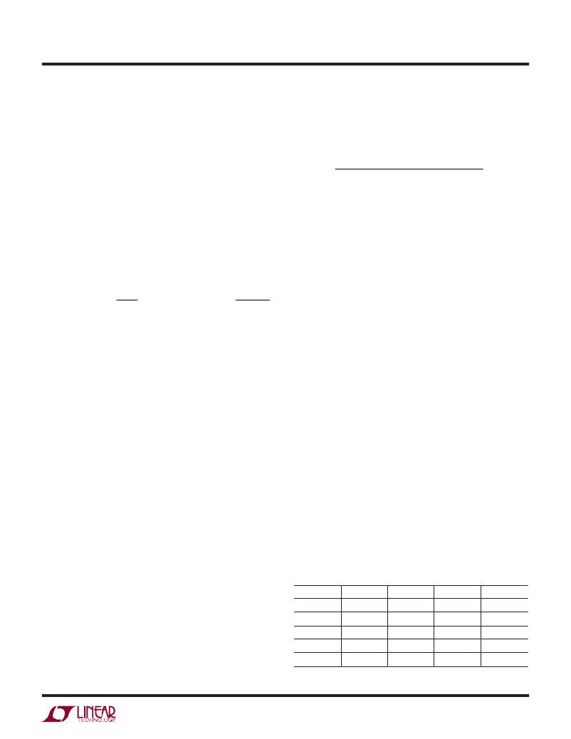
�Tables� 1-4� are� useful� for� selecting� the� resistor� values� for�
�R� REF� and� R� FB� with� no� equations.� The� tables� provide� R� FB� ,�
�R� REF� and� R� TC� values� for� common� output� voltages� and�
�common� winding� ratios.�
�Table� 1.� Common� Resistor� Values� for� 1:1� Transformers�
�V� OUT� (V)� N� PS� R� FB� (kΩ)� R� REF� (kΩ)� R� TC� (kΩ)�
�3.3� 1.00� 18.7� 6.04� 19.1�
�5� 1.00� 27.4� 6.04� 28�
�12� 1.00� 64.9� 6.04� 66.5�
�15� 1.00� 80.6� 6.04� 80.6�
�20� 1.00� 107� 6.04� 105�
�3575f�
�9�
�相关PDF资料 |
PDF描述 |
|---|---|
| LT3579EUFD-1#TRPBF | IC REG MULTI CONFIG SYNC 20QFN |
| LT3580MPMS8E#TRPBF | IC REG BOOST INV SEPIC 2A 8MSOP |
| LT3581IMSE#TRPBF | IC REG MULTI CONFIG ADJ 16MSOP |
| LT3582EUD-5#TRPBF | IC REG BOOST INV +/-5V DL 16QFN |
| LT3587EUD#TRPBF | IC REG BOOST INV ADJ DL 20QFN |
相关代理商/技术参数 |
参数描述 |
|---|---|
| LT3579 | 制造商:LINER 制造商全称:Linear Technology 功能描述:6A Boost/Inverting DC/DC Converter with Fault Protection |
| LT3579-1 | 制造商:LINER 制造商全称:Linear Technology 功能描述:6A Boost/Inverting DC/DC Converter with Fault Protection |
| LT3579EFE#PBF | 功能描述:IC REG MULTI CONFIG SYNC 20TSSOP RoHS:是 类别:集成电路 (IC) >> PMIC - 稳压器 - DC DC 开关稳压器 系列:- 标准包装:250 系列:- 类型:降压(降压) 输出类型:固定 输出数:1 输出电压:1.2V 输入电压:2.05 V ~ 6 V PWM 型:电压模式 频率 - 开关:2MHz 电流 - 输出:500mA 同步整流器:是 工作温度:-40°C ~ 85°C 安装类型:表面贴装 封装/外壳:6-UFDFN 包装:带卷 (TR) 供应商设备封装:6-SON(1.45x1) 产品目录页面:1032 (CN2011-ZH PDF) 其它名称:296-25628-2 |
| LT3579EFE#TRPBF | 功能描述:IC REG MULTI CONFIG SYNC 20TSSOP RoHS:是 类别:集成电路 (IC) >> PMIC - 稳压器 - DC DC 开关稳压器 系列:- 标准包装:20 系列:SIMPLE SWITCHER® 类型:降压(降压) 输出类型:固定 输出数:1 输出电压:12V 输入电压:4 V ~ 60 V PWM 型:电压模式 频率 - 开关:52kHz 电流 - 输出:1A 同步整流器:无 工作温度:-40°C ~ 125°C 安装类型:通孔 封装/外壳:16-DIP(0.300",7.62mm) 包装:管件 供应商设备封装:16-DIP 其它名称:*LM2575HVN-12LM2575HVN-12 |
| LT3579EFE-1#PBF | 功能描述:IC REG MULTI CONFIG SYNC 20TSSOP RoHS:是 类别:集成电路 (IC) >> PMIC - 稳压器 - DC DC 开关稳压器 系列:- 标准包装:250 系列:- 类型:降压(降压) 输出类型:固定 输出数:1 输出电压:1.2V 输入电压:2.05 V ~ 6 V PWM 型:电压模式 频率 - 开关:2MHz 电流 - 输出:500mA 同步整流器:是 工作温度:-40°C ~ 85°C 安装类型:表面贴装 封装/外壳:6-UFDFN 包装:带卷 (TR) 供应商设备封装:6-SON(1.45x1) 产品目录页面:1032 (CN2011-ZH PDF) 其它名称:296-25628-2 |
发布紧急采购,3分钟左右您将得到回复。