- 您现在的位置:买卖IC网 > PDF目录67758 > LT3682IDD#TRPBF (LINEAR TECHNOLOGY CORP) SWITCHING REGULATOR, PDSO12 PDF资料下载
参数资料
| 型号: | LT3682IDD#TRPBF |
| 厂商: | LINEAR TECHNOLOGY CORP |
| 元件分类: | 稳压器 |
| 英文描述: | SWITCHING REGULATOR, PDSO12 |
| 封装: | 3 X 3 MM, LEAD FREE, PLASTIC, DFN-12 |
| 文件页数: | 7/24页 |
| 文件大小: | 253K |
| 代理商: | LT3682IDD#TRPBF |
LT3682
15
3682f
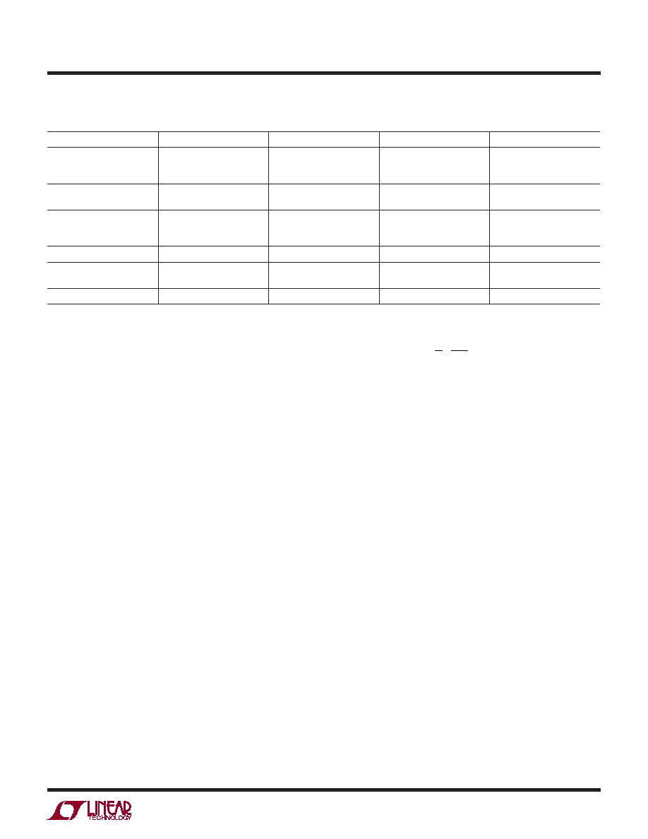
Table 2. Capacitor Vendors
VENDOR
PHONE
URL
PART SERIES
COMMENTS
Panasonic
(714) 373-7366
www.panasonic.com
Ceramic,
Polymer,
Tantalum
EEF Series
Kemet
(864) 963-6300
www.kemet.com
Ceramic,
Tantalum
T494, T495
Sanyo
(408)749-9714
www.sanyovideo.com
Ceramic,
Polymer,
Tantalum
POSCAP
Murata
(408)436-1300
www.murata.com
Ceramic
AVX
www.avxcorp.com
Ceramic,
Tantalum
TPS Series
Taiyo Yuden
(864)963-6300
www.taiyo-yuden.com
Ceramic
APPLICATIONS INFORMATION
When choosing a capacitor, look carefully through the
data sheet to nd out what the actual capacitance is under
operating conditions (applied voltage and temperature).
A physically larger capacitor, or one with a higher voltage
rating, may be required. High performance tantalum or
electrolytic capacitors can be used for the output capacitor.
Low ESR is important, so choose one that is intended for
use in switching regulators. The ESR should be specied
by the supplier, and should be 0.05Ω or less. Such a
capacitor will be larger than a ceramic capacitor and will
have a larger capacitance, because the capacitor must be
large to achieve low ESR. Table 2 lists several capacitor
vendors.
Diode Selection
The catch diode (D1 from block diagram) conducts current
only during switch off time. Average forward current in
normal operation can be calculated from:
II
DC
D AVG
OUT
()
(
)
=
1
where DC is the duty cycle. The only reason to consider a
diode with larger current rating than necessary for nominal
operation is for the case of shorted or overloaded output
conditions. For the worst case of shorted output the diode
average current will then increase to a value that depends on
the following internal parameters: switch current limit, catch
diode (DA pin) current threshold and minimum on-time. The
worstcase(takingmaximumvaluesfortheabovementioned
parameters) is given by the following expression:
IA
V
L
ns
D AVG MAX
IN
()
=+
2
1
2
150
Peak reverse voltage is equal to the regulator input voltage
if it is below the overvoltage protection threshold. This
feature keeps the switch off for VIN > OVLO (41V maxi-
mum). For inputs up to the maximum operating voltage
of 36V, use a diode with a reverse voltage rating greater
than the input voltage. If transients at the input of up to
60V are expected, use a diode with a reverse voltage rat-
ing only higher than the maximum OVLO of 41V. Table 3
lists several Schottky diodes and their manufacturers. If
operating at high ambient temperatures, consider using
a Schottky with low reverse leakage.
Audible Noise
Ceramic capacitors are small, robust and have very
low ESR. However, ceramic capacitors can sometimes
cause problems when used with the LT3682 due to their
piezoelectric nature. When in Burst Mode operation, the
LT3682’s switching frequency depends on the load current,
and at very light loads the LT3682 can excite the ceramic
capacitor at audio frequencies, generating audible noise.
Since the LT3682 operates at a lower current limit during
Burst Mode operation, the noise is typically very quiet. If
this is unacceptable, use a high performance tantalum or
electrolytic capacitor at the output.
相关PDF资料 |
PDF描述 |
|---|---|
| LT3682EDD#TRPBF | SWITCHING REGULATOR, PDSO12 |
| LT3682EDD#PBF | SWITCHING REGULATOR, PDSO12 |
| LT5554IUH#TRPBF | SPECIALTY ANALOG CIRCUIT, PQCC32 |
| LT5554IUH#PBF | SPECIALTY ANALOG CIRCUIT, PQCC32 |
| LTC1421-2.5CSW#PBF | 1-CHANNEL POWER SUPPLY SUPPORT CKT, PDSO24 |
相关代理商/技术参数 |
参数描述 |
|---|---|
| LT3684 | 制造商:LINER 制造商全称:Linear Technology 功能描述:36V, 2A, 2.8MHz Step-Down Switching Regulator |
| LT3684EDD | 制造商:LINER 制造商全称:Linear Technology 功能描述:36V, 2A, 2.8MHz Step-Down Switching Regulator |
| LT3684EDD#PBF | 功能描述:IC REG BUCK ADJ 2A 10DFN RoHS:是 类别:集成电路 (IC) >> PMIC - 稳压器 - DC DC 开关稳压器 系列:- 标准包装:250 系列:- 类型:降压(降压) 输出类型:固定 输出数:1 输出电压:1.2V 输入电压:2.05 V ~ 6 V PWM 型:电压模式 频率 - 开关:2MHz 电流 - 输出:500mA 同步整流器:是 工作温度:-40°C ~ 85°C 安装类型:表面贴装 封装/外壳:6-UFDFN 包装:带卷 (TR) 供应商设备封装:6-SON(1.45x1) 产品目录页面:1032 (CN2011-ZH PDF) 其它名称:296-25628-2 |
| LT3684EDD#PBF | 制造商:Linear Technology 功能描述:DC-DC CONVERTER BUCK 2.8MHZ 制造商:Linear Technology 功能描述:DC-DC CONVERTER, BUCK, 2.8MHZ, DFN-10 |
| LT3684EDD#TRPBF | 功能描述:IC REG BUCK ADJ 2A 10DFN RoHS:是 类别:集成电路 (IC) >> PMIC - 稳压器 - DC DC 开关稳压器 系列:- 标准包装:2,500 系列:- 类型:降压(降压) 输出类型:固定 输出数:1 输出电压:1.2V,1.5V,1.8V,2.5V 输入电压:2.7 V ~ 20 V PWM 型:- 频率 - 开关:- 电流 - 输出:50mA 同步整流器:是 工作温度:-40°C ~ 125°C 安装类型:表面贴装 封装/外壳:10-TFSOP,10-MSOP(0.118",3.00mm 宽)裸露焊盘 包装:带卷 (TR) 供应商设备封装:10-MSOP 裸露焊盘 |
发布紧急采购,3分钟左右您将得到回复。