- 您现在的位置:买卖IC网 > PDF目录15310 > LT3759HMSE#PBF (Linear Technology)IC REG CTRLR BST INV PWM 12-MSOP PDF资料下载
参数资料
| 型号: | LT3759HMSE#PBF |
| 厂商: | Linear Technology |
| 文件页数: | 18/32页 |
| 文件大小: | 0K |
| 描述: | IC REG CTRLR BST INV PWM 12-MSOP |
| 标准包装: | 37 |
| PWM 型: | 电流模式 |
| 输出数: | 1 |
| 频率 - 最大: | 1MHz |
| 电源电压: | 1.6 V ~ 42 V |
| 降压: | 无 |
| 升压: | 是 |
| 回扫: | 无 |
| 反相: | 是 |
| 倍增器: | 无 |
| 除法器: | 无 |
| Cuk: | 无 |
| 隔离: | 无 |
| 工作温度: | -40°C ~ 150°C |
| 封装/外壳: | 12-TSSOP (0.118",3.00mm 宽)裸露焊盘 |
| 包装: | 管件 |
第1页第2页第3页第4页第5页第6页第7页第8页第9页第10页第11页第12页第13页第14页第15页第16页第17页当前第18页第19页第20页第21页第22页第23页第24页第25页第26页第27页第28页第29页第30页第31页第32页
�� �
�
�LT3759�
�APPLICATIONS� INFORMATION�
�D� 2MAX� ?� V� 2� IN(MIN)� ?� η�
�2� ?� P� OUT(MAX)� ?� f� OSC�
�D2� 2� ?� (V� OUT� +� V� D� )�
�2� ?� I� OUT(MAX)� ?� f� OSC�
�N� P� L� P�
�I� LP(MAX)� =� I� SW(MAX)� =�
�I� LS(MAX)� =� I� D(MAX)� =�
�I� LP(RMS)� =� 2� ?� I� LP(MAX)� ?�
�I� LS(RMS)� =� 2� ?� I� LS(MAX)� ?�
�V� 2SN� ?� V� SN� ?� V� OUT� ?�
�R� SN� =� 2� ?�
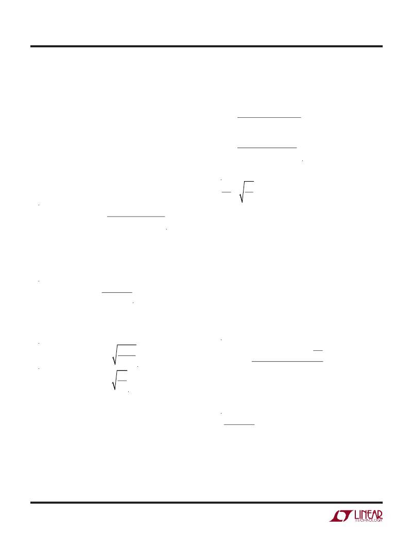
�FlybackConverter:TransformerDesignfor�
�Discontinuous� Mode� Operation�
�The� transformer� design� for� discontinuous� mode� of� opera-�
�tion� is� chosen� as� presented� here.� According� to� Figure� 7,�
�the� minimum� D3� (D3� MIN� )� occurs� when� the� converter�
�has� the� minimum� V� IN� and� the� maximum� output� power�
�(P� OUT� ).� Choose� D3� MIN� to� be� equal� to� or� higher� than� 10%�
�to� guarantee� the� converter� is� always� in� discontinuous�
�mode� operation� (choosing� higher� D3� allows� the� use� of� low�
�inductances,� but� results� in� a� higher� switch� peak� current).�
�The� user� can� choose� a� D� MAX� as� the� start� point.� Then,� the�
�maximum� average� primary� currents� can� be� calculated� by�
�the� following� equation:�
�P� OUT(MAX)�
�D� MAX� ?� V� IN(MIN)� ?� η�
�where� h� is� the� converter� efficiency.�
�If� the� flyback� converter� has� multiple� outputs,� P� OUT(MAX)�
�is� the� sum� of� all� the� output� power.�
�The� maximum� average� secondary� current� is:�
�I� OUT(MAX)�
�D2�
�where:�
�D2� =� 1� –� D� MAX� –� D3�
�the� primary� and� secondary� RMS� currents� are:�
�D� MAX�
�3�
�D2�
�3�
�According� to� Figure� 7,� the� primary� and� secondary� peak�
�currents� are:�
�I� LP(PEAK)� =� I� SW(PEAK)� =� 2� ?� I� LP(MAX)�
�I� LS(PEAK)� =� I� D(PEAK)� =� 2� ?� I� LS(MAX)�
�The� primary� and� second� inductor� values� of� the� flyback�
�converter� transformer� can� be� determined� using� the� fol-�
�lowing� equations:�
�L� P� =�
�L� S� =�
�The� primary� to� second� turns� ratio� is:�
�=�
�N� S� L� S�
�Flyback� Converter:� Snubber� Design�
�Transformer� leakage� inductance� (on� either� the� primary� or�
�secondary)� causes� a� voltage� spike� to� occur� after� the� MOS-�
�FET� turn-off.� This� is� increasingly� prominent� at� higher� load�
�currents,� where� more� stored� energy� must� be� dissipated.�
�In� some� cases� a� snubber� circuit� will� be� required� to� avoid�
�overvoltage� breakdown� at� the� MOSFET’s� drain� node.� There�
�are� different� snubber� circuits,� and� Application� Note� 19� is�
�a� good� reference� on� snubber� design.� An� RCD� snubber� is�
�shown� in� Figure� 6.�
�The� snubber� resistor� value� (R� SN� )� can� be� calculated� by� the�
�following� equation:�
�N� P�
�N� S�
�I� 2SW(PEAK)� ?� L� LK� ?� f� OSC�
�where� V� SN� is� the� snubber� capacitor� voltage.� A� smaller�
�V� SN� results� in� a� larger� snubber� loss.� A� reasonable� V� SN� is�
�2� to� 2.5� times� of:�
�V� OUT� ? N� P�
�N� S�
�3759fc�
�18�
�For� more� information� www.linear.com/3759�
�相关PDF资料 |
PDF描述 |
|---|---|
| LT1725CGN#TR | IC REG CTRLR FLYBK ISO CM 16SSOP |
| UCA2V330MHD1TN | CAP ALUM 33UF 350V 20% RADIAL |
| B41042A3827M | 820UF 10V 10X20 SINGLE END |
| LT3757HMSE#TRPBF | IC REG CTRLR PWM CM 10-MSOP |
| LTC3830-1ES8#TRPBF | IC REG CTRLR BUCK PWM VM 8-SOIC |
相关代理商/技术参数 |
参数描述 |
|---|---|
| LT3759IMSE#PBF | 功能描述:IC REG CTRLR BST INV PWM 12-MSOP RoHS:是 类别:集成电路 (IC) >> PMIC - 稳压器 - DC DC 切换控制器 系列:- 标准包装:2,500 系列:- PWM 型:电流模式 输出数:1 频率 - 最大:500kHz 占空比:96% 电源电压:4 V ~ 36 V 降压:无 升压:是 回扫:无 反相:无 倍增器:无 除法器:无 Cuk:无 隔离:无 工作温度:-40°C ~ 125°C 封装/外壳:24-WQFN 裸露焊盘 包装:带卷 (TR) |
| LT3759IMSE#TRPBF | 功能描述:IC REG CTRLR BST INV PWM 12-MSOP RoHS:是 类别:集成电路 (IC) >> PMIC - 稳压器 - DC DC 切换控制器 系列:- 标准包装:2,500 系列:- PWM 型:电流模式 输出数:1 频率 - 最大:500kHz 占空比:96% 电源电压:4 V ~ 36 V 降压:无 升压:是 回扫:无 反相:无 倍增器:无 除法器:无 Cuk:无 隔离:无 工作温度:-40°C ~ 125°C 封装/外壳:24-WQFN 裸露焊盘 包装:带卷 (TR) |
| LT375B | 制造商:EDSYN 功能描述:TIP SPADE 1.5X12.2MM |
| LT375-C | 制造商:EDSYN 功能描述: |
| LT376 | 制造商:EDSYN 功能描述: 制造商:EDSYN 功能描述:SOLDERING TIP, Tip / Nozzle Length:0.48" |
发布紧急采购,3分钟左右您将得到回复。