参数资料
| 型号: | LT6301IFE |
| 厂商: | Linear Technology |
| 文件页数: | 6/16页 |
| 文件大小: | 0K |
| 描述: | IC XDSL LINE DRIVER DUAL 28TSSOP |
| 标准包装: | 50 |
| 类型: | 驱动器 |
| 驱动器/接收器数: | 2/0 |
| 规程: | xDSL |
| 电源电压: | 5 V ~ 12 V |
| 安装类型: | 表面贴装 |
| 封装/外壳: | 28-SOIC(0.173",4.40mm 宽)裸露焊盘 |
| 供应商设备封装: | 28-TSSOP 裸露焊盘 |
| 包装: | 管件 |
| 产品目录页面: | 1321 (CN2011-ZH PDF) |
14
LT6301
sn6301 6301f
APPLICATIO S I FOR ATIO
WU
UU
from the line is sensed across the back termination resis-
tors. With positive feedback, signals are present on both
ends of the RBT resistors, reducing the sensed amplitude.
Extra gain may be required in the receive channel to
compensate, or a completely separate receive path may be
implemented through a separate line coupling transformer.
Considerations for Fault Protection
The basic line driver design, shown on the front page of
this data sheet, presents a direct DC path between the
outputs of the two amplifiers. An imbalance in the DC
biasing potentials at the noninverting inputs through
either a fault condition or during turn-on of the system can
create a DC voltage differential between the two amplifier
outputs. This condition can force a considerable amount
of current to flow as it is limited only by the small valued
back-termination resistors and the DC resistance of the
transformer primary. This high current can possibly cause
the power supply voltage source to drop significantly
impacting overall system performance. If left unchecked,
the high DC current can heat the LT6301 to thermal
shutdown.
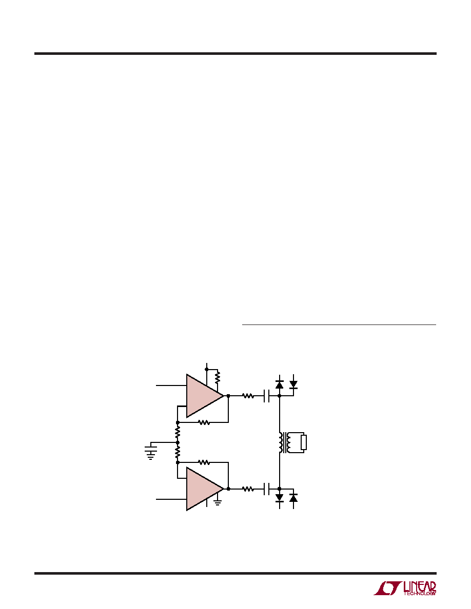
Using DC blocking capacitors, as shown in Figure 15, to
AC couple the signal to the transformer eliminates the
possibility for DC current to flow under any conditions.
These capacitors should be sized large enough to not
impair the frequency response characteristics required for
the data transmission.
Another important fault related concern has to do with
very fast high voltage transients appearing on the tele-
phone line (lightning strikes for example). TransZorbs
,
varistors and other transient protection devices are often
used to absorb the transient energy, but in doing so also
create fast voltage transitions themselves that can be
coupled through the transformer to the outputs of the line
driver. Several hundred volt transient signals can appear
at the primary windings of the transformer with current
into the driver outputs limited only by the back termination
resistors. While the LT6301 has clamps to the supply rails
at the output pins, they may not be large enough to handle
the significant transient energy. External clamping diodes,
such as BAV99s, at each end of the transformer primary
help to shunt this destructive transient energy away from
the amplifier outputs.
TransZorb is a registered trademark of General Instruments, GSI
Figure 15. Protecting the Driver Against Load Faults and Line Transients
6301 F15
+
–
1/4
LT6301
–IN
–
+
1/4
LT6301
+IN
12V
SHDN
–12V
12.7
0.1
F
12V –12V
24.9k
1:2
LINE
LOAD
110
1000pF
110
1k
12.7
SHDNREF
0.1
F
12V –12V
BAV99
相关PDF资料 |
PDF描述 |
|---|---|
| LT8500IUHH#TRPBF | IC PWM GENERATOR 56-QFN |
| LTC1096IN8#PBF | IC A/D CONV 8BIT SRL IN/OUT 8DIP |
| LTC1099ACN#PBF | IC A/D CONV 8BIT HI-SPEED 20-DIP |
| LTC1197IMS8#PBF | IC ADC 10BIT 500KHZ SHTDWN 8MSOP |
| LTC1198-1BCS8#PBF | IC ADC 8BIT 750KHZ SAMPL 8-SOIC |
相关代理商/技术参数 |
参数描述 |
|---|---|
| LT6301IFE#TR | 功能描述:IC XDSL LINE DRIVER DUAL 28TSSOP RoHS:否 类别:集成电路 (IC) >> 接口 - 驱动器,接收器,收发器 系列:- 标准包装:250 系列:- 类型:收发器 驱动器/接收器数:2/2 规程:RS232 电源电压:3 V ~ 5.5 V 安装类型:表面贴装 封装/外壳:16-TSSOP(0.173",4.40mm 宽) 供应商设备封装:16-TSSOP 包装:带卷 (TR) |
| LT6301IFE#TRPBF | 功能描述:IC XDSL LINE DRIVER DUAL 28TSSOP RoHS:是 类别:集成电路 (IC) >> 接口 - 驱动器,接收器,收发器 系列:- 标准包装:250 系列:- 类型:收发器 驱动器/接收器数:2/2 规程:RS232 电源电压:3 V ~ 5.5 V 安装类型:表面贴装 封装/外壳:16-TSSOP(0.173",4.40mm 宽) 供应商设备封装:16-TSSOP 包装:带卷 (TR) |
| LT630Z | 制造商:SEOUL 制造商全称:Seoul Semiconductor 功能描述:GREEN OVAL LAMP LED |
| LT631 | 制造商:SEOUL 制造商全称:Seoul Semiconductor 功能描述:BLUE OVAL LAMP LED |
| LT6350 | 制造商:LINER 制造商全称:Linear Technology 功能描述:18-Bit, 2.5Msps SAR ADC with Pin-Configurable Analog |
发布紧急采购,3分钟左右您将得到回复。